

R4-EM

R4-EM
- Construction: High-strength steel, zinc-plated housing and components.
- Operation Voltage: 12 to 24 Volt DC.
- Current: Typical operating current is less than 500mA at 12 VDC, with a peak/stall current of 1A.
- Microswitch Rating: 3A at 12VDC maximum.
- Push-to-close electronic release with a versatile rotary mechanism.
- Concealed latching with microprocessor control and minimal power draw.
- Optional internal microswitch for latch open/close output signal.
- Mounting holes and dimensions are provided for precise installation.
- Optional mechanical override and cable mounting kits are available.
- Auto Relock: The latch unlocks and releases the cam to open the door, automatically cycling through unlatched and relatched states.
- Delayed Relock: The latch remains unlocked as long as the signal is present, allowing manual door operation.
Catalog excerpts

R4-EM 1 & 2 Series Electronic Rotary Latch All-metal construction Electronic access with internal motor control Mounting holes (see part number table) 9.1 (.36) 9.5 (.37) ACTUAL SIZE DOOR OPEN 39.68 (1.56) Latch Wiring Connections With connector Molex Microfit 3.0 series PIN 3 PIN 2 PIN 1 PIN 6 PIN 3 PIN 5 PIN 2 Part Number Selection PIN 4 PIN 1 69.0 Mounting h (2.71) Mechanical Cam (see Part Num trigger Table) 12.5 (.49) 15.0 (.59) Mechanical trigger Optional over-ride cable 42.5 (1.67 mounting bracket 150 (5.9) Optional over-ride cable Without connector mounting bracket Other options available. For complete details on variety, part numbers, installation and specification, go to B Base Mounting Style 1 1/4 - 20 thread 2 M6 thread 3 Ø 7.0 (.27) thru hole A Alternate Configurations None Standard configuration 2 Strong (kick out) cam spring (delayed relock) 3 High strength cam 4 High strength cam with strong (kick out) cam spring (delayed relock) Dimensions in millimeters (inch) unless otherwise stated 38.1 16.0 (1.50) (.63) 27.7 (1.09) M8 25.4 x 1.25 (1.00) Ø3.28 (.129) x 2 through holes for optiona Thread mechanical override mounting brackets. Accommodates standard 1/8” blind rivets Max. insertion depth 5mm O-Ring Ø 9.5 Ø 25.4 Packaging Options P (.37) (1.00) Washer None Individually packaged 430 (16.9) T Trigger Styles R1 Auto relock, rear trigger, with kick-out spring R2 Delayed relock, rear trigger, with light spring Mounting holes (see Part Number Table) 42.5 (1.67) Wires Striker bolt Striker bolt (sold separately) • igh strength, steel H construction • perates against high O mechanical loads • Push-to-close, electronic release • Versatile rotary mechanism • Concealed latching • Microprocessor control • Minimal power draw • Simple mechanical override • Optional internal microswitch for latch open/close output signal Striker Bulk packaged 1 bolt C Connector Options 1 With connector 2 Without connector S Switch Options 3 No switch 6 Int
Open the catalog to page 1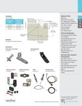
Material & Finish Installation Panel Preparation Base Mounting Style Recommended minimum mounting hole Thru hole 42.5 ±0.2 (1.673 ±.008) Mounting holes (see table) Accessories Cable Mounting Kit See page 35 Striker Bolt or Cast Striker See page 35 Electronic Actuator: Housing: PC/ABS Cam / follower: Acetal Electrical Specifications Recommended Operating Voltage: 12 to 24 Volt DC Typical Operating Current: Less than 500mA at 12 VDC Peak/Stall Operating Current: 1 A Standby Current: 185uA Input Signal Current Draw: 25mA **Optional microswitch closes upon latch closure Microswitch Rating: 3A at...
Open the catalog to page 2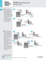
Signal device Operation - Auto relock 1. he signal unlocks the R4-EM T latch and releases the spring loaded cam which rotates out to push a lightweight door open. The mechanism will cycle through unlatched then relatched state automatically, regardless of input signal on time. 2. ush door closed to engage P striker after unlock time has expired. Striker will rotate cam to closed position. R4-EM Electronic Rotary Latch LOCK LATCH Operating instructions Signal device Remove signal to lock R4-EM Latch OPEN LATCH Signal to unlock the R4-EM latch Signal device Optional mechanical over-ride LOCK LATCH...
Open the catalog to page 3
Striker Bolt - Large Part number R4-90-121-10 Striker Bolt - Small Part number R4-90-511-10 Material and Finish Striker bolts: Steel, zinc plated Cast strikers: Zinc alloy Cable mounting kits: Glass-filled nylon, black *Note: Latch and striker installation details can be found on the latch trade drawing at www.southco.com. Cast Striker with Door Sensor Part number R4-90-804-10* Cast Striker without Door Sensor Part number R4-90-800-10* Dimensions in millimeters (inch) unless otherwise stated
Open the catalog to page 4All Southco Asia Ltd catalogs and technical brochures
 R4 Rotary Latch
14 Pages
 47 Captive Screws
36 Pages
 CB Hinge
2 Pages
 E6 Hinge
2 Pages
 DM Inserts
1 Page
 GA Joint
1 Page
 C5 - Sealed Lever Latches
2 Pages
 A7 Compression Latch
2 Pages
 C2 Compression Latch
1 Page


