Catalog excerpts

User’s guide GF-2062 © 2018 SOURCETRONIC. All rights reserved. 3
Open the catalog to page 1
This equipment should be operated only by qualified and duly trained people, closely observing the corresponding safety regulations and instructions contained in the present User guide. It should be checked that the item to be measured is voltage free. Before starting with the measurements, be sure that the battery is well charged and that the line voltage is between specified limits. Do not connect or disconnect the test leads during the measurement. There are no adjustable parts or parts that can be replaced by the user within the equipment. Taking out the Control Panel in order to have...
Open the catalog to page 2
Used symbols Caution, refer to User Guide. Battery. Printer. USB (Universal Serial Bus). 30 V max. (to ground): indicates the maximum potential allowed in the terminals during resistance measurements. Ground protection: the terminal identified by this symbol is intended for connection to an external conductor for protection against electric shock in case of failure, or the terminal of a ground protection electrode. Equipment complies with current EU Directives. Double insulation: symbol indicates that the equipment is classified as Class II (double isolated). The rubbish bin with a line...
Open the catalog to page 3
1. Description The MPK-256 micro-ohmmeter is a portable, microprocessor controlled instrument, used to accurately measure very low contact resistances of breakers and switches, busbars, transformers and engines windings, etc, with test currents from 1 mA to 10 A. Microprocessor controlled Kelvin architecture (four-terminal method) Digital reading, alphanumeric display Up to 4½ digits readings Powered by rechargeable battery 1 µΩresolution 2000 Ωmaximum reading Up to 10 A current Remote control through an Android app 1.1. Operating principle This device uses the Kelvin...
Open the catalog to page 5
Power cord connector. Auxiliary supply connector. Battery charge indicator. Selector of ranges and currents. Test current control. Battery key. To measure the battery charge condition.
Open the catalog to page 6
3. Power supply Mains supply or internal battery powered Battery: LFP, rechargeable, 12 V - 6000 mAh. Mains: 220 - 240 V~. Auxiliary supply: 12 V. 3.1. Battery condition The charge condition of the battery can be verified before or during the resistance measurement. In order to achieve that, the operator has to press the battery key while the equipment is turned on. The bargraph shows remaining charge as a percentile value. 3.2. Battery charger Charging procedure: Check that the On/Off Connect the equipment to the mains supply. The battery charge indicator ( ) will keep on lightning...
Open the catalog to page 7
The rechargeable battery has no "memory effect" so it can be charged as many times as desired. On the other hand, its useful life is significantly reduced if it is allowed to remain totally discharged. To avoid this effect, charge the battery before storing the equipment and do not allow more than 30 days to pass without repeating the charging process, even if the instrument has not been used (The battery loses part of its charge when it is stored). At the end of its useful life, the battery must be recycled or disposed of properly to preserve the environment. 3.3. Auxiliary power The...
Open the catalog to page 8
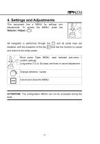
4. Settings and Adjustments This equipment has a MENU for settings and adjustments. To access the MENU, press the Selector / Adjust ( ). All navigation is performed through the disabled, with the exception of the key and all panel keys are that has the function to cancel and return to the initial screen. Short press: Open MENU, open selected sub-menu / confirm settings. Long press (1.5 s): Go back one level or cancel adjustment. Change selection / values Cancel and close the MENU ATTENTION: The configuration MENU can not be accessed during the tests.
Open the catalog to page 9
Filter Auto save SUBMENU AUTO SAVE Save the last measured value in the internal memory when the test is finished. Allows you to change the interface language between: English, Spanish and Portuguese. SETTINGS SET DATE FORMAT Selecting the date format. Selecting the time format. DATE ADJUST TIME ADJUST DISPLAY ADJUST SYSTEM INFO
Open the catalog to page 10
5. Measurement • The User Manual and its respective safety precautions must be read and understood before using the micro-ohmmeter. • The usual safety precautions and safety regulations must be strictly observed. • It should be checked that the item to be measured is voltage free. • To ensure safety, use only the accessories supplied by the manufacturer. Before turning the equipment On, connect the test leads to the item to be measured and to the front panel terminals. The alligator clamps in the drawings are only for illustration
Open the catalog to page 11
Measurement with potential risk Ex .: High voltage circuit breaker under external influence of electromagnetic fields from nearby energized devices. The alligator clamps in the drawings are only for illustration. The safety ground terminal must be connected before making the other connections to the equipment. 2. Turn on the device with the On / Off key ( The display of the equipment will show the presentation message MPK256. The AUTO VERIFICATION message will appear next and then PRESS START. Select the range and current (
Open the catalog to page 12
The message LOW CURRENT will appear. Turning the control clockwise will increase the current until reaching the desired stable value measured on the display or in the bargraph current indicator. When the current value is greater than 20% of the nominal value of the scale, the display will indicate the measured resistance value. To finish the measurement press. WITHOUT PRESSING . When you finish all measurements, turn off the Caution: Never connect or disconnect the test leads with the equipment in operation. If you have to make any changes to the connection, it must be done with the...
Open the catalog to page 13
6. Display messages MPK-256 When turning the equipment On using the On/Off switch, this introductory message appears for a while. During that time, the equipment carries out some functional checking. AUTO CHECK Indicates that the equipment is performing internal checks. PRESS START Indicates that the equipment is able to start a test, for which the operator must press the key . LOW CURRENT This warning indicates that the test current is insufficient to perform the measurement. The control must be turned clockwise to increase current. I=MAX Indicates that the current reached the maximum...
Open the catalog to page 14All Sourcetronic GmbH catalogs and technical brochures
-
MPK-256
20 Pages
-
Manual ST2822 LCR Meter Series
99 Pages
-
Manual ST2829 LCR Meter Series
119 Pages
-
Manual ST2827 LCR Meter Series
118 Pages
-
Manual ST2830 LCR Meter Series
127 Pages
-
Manual ST500 Frequency Inverter
180 Pages
-
Measurement Technology
20 Pages


