
- Catalogs
- SOPAP Automation
- Serie P65-130

Serie P65-130

Serie P65-130
- Number of Stops: 1, 2, 3, 4, 6, 8 (additional numbers available on request)
- Angle of Oscillation: 15°, 20°, 30°, 45° (additional angles available on request)
- Dimensions: Provided for sizes P 65, P 80, P 105, and P 130, with specific measurements for various parameters such as a, b, c, Ø d k6, e, f, g, h, i, j, k, l, m, n, p, r, S, U, Ø d1 h6, f1, and weight.
- Max. Allowable Axial Load Input Shaft (ABE): Ranges from 16 daN to 80 daN depending on size.
- Max. Allowable Radial Load Input Shaft (RBE): Ranges from 65 daN to 250 daN depending on size.
- Max. Allowable Tilting Torque Input Shaft (KME): Ranges from 2.6 daNm to 27.5 daNm depending on size.
- Max. Allowable Axial Load Output Shaft (ABA): Ranges from 32 daN to 160 daN depending on size.
- Max. Allowable Radial Load Output Shaft (RBA): Ranges from 65 daN to 250 daN depending on size.
- Max. Allowable Tilting Torque Output Shaft (KMA): Ranges from 2.6 daNm to 27.5 daNm depending on size.
- Additional Fixed Torque (Mf1): Ranges from 1.2 daNm to 3.5 daNm depending on size.
- Includes two coupled cams and a radial roller gear hub for intermittent command of division plates, conveyors, etc.
- Vibrationless positive motion and lifetime grease.
- Housing machined on all faces allowing all mounting positions.
- Possible supply of single parts (cams and turret).
- Available with gear reducer or motor gear reducer.
- Avoid mounting elastic elements on input and output shafts.
- Inversion of input shaft rotation will also invert output shaft rotation without changing kinematical characteristics.
Catalog excerpts
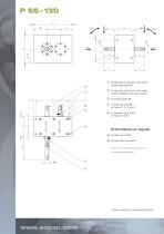
1 Positioning of the key in the dwell phase (stop period) 2 Positioning of the key in the dwell phase (middle of the stop period) 3 Threaded holes U 4 4 fastening holes S on faces C, D, E and F 5 6 assembly stud holes on faces D and F Extra features on request A Double input shaft B Torque limiter at output Dimensions without tolerances according to JS 13 Key normalised under DIN 6885 3 years warranty on standard products.
Open the catalog to page 2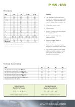
P 65 - 130 Dimensions Size a b c Ø d k6 e f g h i j k l m n p r S U Ø d1 h6 f1 Weight (kg) Lifetime grease Housing machined on all faces allowing all mounting positions Possible supply of single parts (cams and turret) Available with gear reducer or motor gear reducer Please avoid the mounting of elastic elements on the input and output shafts Dimensions for reducers and motors: please contact us. Vibrationless positive motion d1 and f1 are the biggest dimensions available on request. This intermittent motion mechanism includes two coupled cams and a radial roller gear hub for the intermittent...
Open the catalog to page 3All SOPAP Automation catalogs and technical brochures
 Serie MI
3 Pages
 Serie M-MV
5 Pages
 Serie GY
2 Pages
 Manufacturing program
6 Pages
- Handling manipulator
- Linear axis
- Electric linear axis
- Index unit
- Rotary indexing table
- Cam indexer
- Rotary indexer
- Electric rotary indexing table
- Rotary manipulator
- Horizontal rotary indexing table
- Motor-driven rotary indexing table
- Machine indexer
- Machine tool rotary indexing table
- Cam rotary indexing table
- Oscillating indexer
- Heavy load indexer
- Globoidal cam indexer
- Linear array manipulator
- Right-angle indexer
- Globoidal cam rotary indexing table