
- Catalogs
- Sony Semiconductors
- Ultra-High-Speed Synchronous SRAMs CXK77K18R320GB

- Products
- Catalogs
- News & Trends
- Exhibitions
Ultra-High-Speed Synchronous SRAMs CXK77K18R320GB

Ultra-High-Speed Synchronous SRAMs CXK77K18R320GB
- Operates at 333 MHz with a single 1.8V power supply.
- Supports 3 speed bins with cycle times of 3.0ns, 3.3ns, and 4.0ns.
- Features HSTL-compatible I/O interface and programmable output driver impedance.
- Includes JTAG boundary scan interface using IEEE standard 1149.1 protocol.
- Read and write operations are synchronized with the rising edge of the K clock.
- Sleep mode is activated via the ZZ input, preserving memory contents while reducing power consumption.
- Output driver impedance is programmable and controlled by an external resistor connected to the ZQ pin.
- Supply voltage ranges from 1.7V to 1.9V, with output supply voltage from 1.4V to VDD.
- Input and output leakage currents are specified, with typical operating current at 650 mA for the fastest speed bin.
- AC characteristics include input cycle time, clock pulse widths, and setup/hold times for various signals.
- CIN: 3.5pF to 4.0pF
- CKIN: 3.5pF to 4.5pF
- COUT: 4.5pF to 5.0pF
- tKHQV: Changed from 1.5ns to 1.6ns
- tKHQZ: Changed from 1.7ns to 1.8ns
- Added a note regarding lead content in solder balls.
- Revision 0.8 dated December 8, 2004, includes modifications to AC Electrical Characteristics and additional notes.
Catalog excerpts
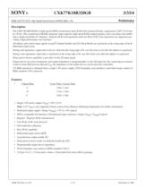
32Mb LW R-R HSTL High Speed Synchronous SRAM (2Mb x 18) The CXK77K18R320GB is a high speed CMOS synchronous static RAM with common I/O pins, organized as 2,097,152 wordsby 18 bits. This synchronous SRAMs integrates input registers, high speed RAM, output registers, and a one-deep write buffer onto a single monolithic IC. Register - Register (R-R) read operations and Late Write (LW) write operations are supported, pro-viding a high-performance user interface. All address and control input signals except G (Output Enable) and ZZ (Sleep Mode) are registered on the rising edge of the Kdifferential input clock. During read operations, output data is driven valid from the rising edge of K, one full clock cycle after the address is registered.During write operations, input data is registered on the rising edge of K, one full clock cycle after the address is registered.Sleep (power down) capability is provided via the ZZ input signal. Output drivers are series terminated, and output impedance is programmable via the ZQ input pin. By connecting an externalcontrol resistor RQ between ZQ and V > SS , the impedance of the output drivers can be precisely controlled.333 MHz operation is obtained from a single 1.8V power supply. JTAG boundary scan interface is provided using a subset ofIEEE standard 1149.1 protocol. > 3 Speed Bins Cycle Time / Access Time -3 3.0ns / 1.6ns-33 3.3ns / 1.6ns -4 4.0ns / 2.0ns?Single 1.8V power supply (V > DD ): 1.8V ձ 0.1V Note : 2.5V V > DD is also supported. Please contact Sony Memory Marketing Department for further information.?Dedicated output supply voltage (V > DDQ ): 1.5V to 1.8V typical?HSTL-compatible I/O interface with dedicated input reference voltage (V > REF ): V > DDQ /2 typical?Register - Register (R-R) read protocol?Late Write (LW) write protocol?Full read/write coherency ?Byte Write capability?Differential input clocks (K/K )?Asynchronous output enable (G )?Sleep (power down) mode via dedicated mode pin (ZZ)?Programmable output driver impedance?JTAG boundary scan (subset of IEEE standard 1149.1) ?119 pin (7x17), 1.27mm pitch, 14mm x 22mm Ball Grid Array (BGA) package > 32Mb LW R-R, rev 0.81 / 23December 8, 2004 size="-1">
Open the catalog to page 1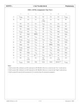
DDQ SASANCSASAV > DDQ BNCSASASA(32M)SASANCCNCSASAV > DD SASANCDDQbNCV > SS ZQV > SS DQaNCENCDQbV > SS SS V > SS NCDQaFV > DDQ NCV > SS G V > SS DQaV > DDQ GNCDQbSBW bNCV > SS NCDQaHDQbNCV > SS NCV > SS DQaNCJV > DDQ V > DD V > REF V > DD V > REF V > DD V > DDQ KNCDQbV > SS KV > SS NCDQaLDQbNCV > SS K SBW aDQaNCMV > DDQ DQbV > SS SW V > SS NCV > DDQ NDQbNCV > SS SAV > SS DQaNCPNCDQbV > SS SAV > SS NCDQaRNCSAM1 > (1) V > (2) DD M2 SANCTNCSA(x18)SANC(x36)SASA(x18)ZZUV > (3) DDQ TMSTDITCKTDORSVD V > DDQ Notes :1. Pad Location 3R is defined as an M1 mode pin in LW SRAMs. However, it must be tied Γlow...
Open the catalog to page 2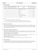
x(t (t OperationDQ(t > n )SW (t > n )SBW > n )G > n )DQ(t > n+1 )X1XXXXSleep (Power Down) ModeHi - ZHi - Z ↑ 01XXXDeselect***Hi - Z ↑ 001X1ReadHi - ZHi - Z ↑ 001X0Read***Q(t > n ) ↑ 0000XWrite All Bytes***D(t > n ) ↑ 000XXWrite Bytes With SBW x = 0***D(t > n ) ↑ 0001XAbort Write***Hi - Z Notes: 1.1Ӕ = input highӔ; 0Ӕ = input lowӔ; XӔ = input donӒt care.2. ԓ*** indicates that the input requirement or output state is determined by the previous operation.3.DQs are tri-stated in response to Write and Deselect commands, one cycle after the command is sampled. > Sleep (power down) mode is provided...
Open the catalog to page 4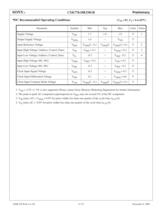
(V > o SS = 0V, T > A = 0 to 85 C) > DD 1.71.81.9V1Output Supply VoltageV > DDQ 1.4---V > DD VInput Reference VoltageV > REF V > DDQ /2 - 0.1V > DDQ /2V > DDQ /2 + 0.1V2Input High Voltage (Address, Control, Data)V > IH V > REF + 0.1---V > DDQ + 0.3V3Input Low Voltage (Address, Control, Data)V > IL -0.3---V > REF - 0.1V4Input High Voltage (M1, M2)V > MIH V > REF + 0.3---V > DD + 0.3VInput Low Voltage (M1, M2)V > MIL -0.3---V > REF - 0.3VClock Input Signal VoltageV > KIN -0.3---V > DDQ + 0.3VClock Input Differential VoltageV > DIF 0.2---V > DDQ + 0.6VClock Input Common Mode VoltageV > CM V > DDQ...
Open the catalog to page 6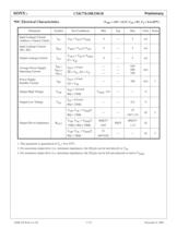
(V > o DD = 1.8V α 0.1V, V > SS = 0V, T > A = 0 to 85 C) > LI V > IN = V > SS to V > DDQ -5---5uAInput Leakage Current (M1, M2)I > MLI V > MIN = V > SS to V > DD -5---5uAOutput Leakage CurrentI V > OUT = V > SS to V > DDQ LO -5---5uAAverage Power Supply Operating CurrentI G = V > IH DD-3 I = 0 mASS ------ --------- ---650600 540mAPower SupplyStandby CurrentI I > OUT DD-33 I > DD-4 = V > IL , ZZ = V > IL I > OUT = 0 mAZZ = V > SB ------180mA1Output High VoltageV > IH I > OH = -6.0 mARQ = 250 > OH V - 0.4------VOutput Low VoltageV Ω > DDQ I > OL = 6.0 mARQ = 250 > OL ------0.4VOutput Driver ImpedanceR...
Open the catalog to page 7
ItemSymbolConditionsUnitsNotesInput Reference VoltageV > REF 0.75VInput High LevelV > IH 1.25VInput Low LevelV > IL 0.25VInput Rise & Fall Time2.0V/nsInput Reference Level0.75V Clock Input High VoltageV > KIH 1.25VV > DIF = 1.0VClock Input Low VoltageV > KIL 0.25VV > DIF = 1.0VClock Input Common Mode VoltageV > CM 0.75VClock Input Rise & Fall Time2.0V/nsClock Input Reference LevelK/K crossVOutput Reference Level0.75VOutput Load ConditionsRQ = 250 Ω See Figure 1below >
Open the catalog to page 9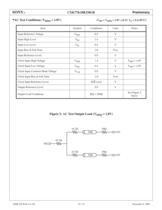
ItemSymbolConditionsUnitsNotesInput Reference VoltageV > REF 0.9VInput High LevelV > IH 1.4VInput Low LevelV > IL 0.4VInput Rise & Fall Time2.0V/nsInput Reference Level0.9V Clock Input High VoltageV > KIH 1.4VV > DIF = 1.0VClock Input Low VoltageV > KIL 0.4VV > DIF = 1.0VClock Input Common Mode VoltageV > CM 0.9VClock Input Rise & Fall Time2.0V/nsClock Input Reference LevelK/K crossVOutput Reference Level0.9VOutput Load ConditionsRQ = 250 ТĦ See Figure 2below >
Open the catalog to page 10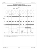
DummyDummy ReadReadReadReadReadWriteWriteWriteReadRead Read > t > KHKH t > KHKL t > KLKH t > AVKH t > KHAX IL t > WVKH t > KHWX t > WVKH t > KHWX t > GLQV t > GHQZ t > GLQX t > KHQV t > KHQX t > KHQZ t > DVKH t > KHDX t > KHQX1
Open the catalog to page 12All Sony Semiconductors catalogs and technical brochures
 IMX901-AMR
2 Pages
 IMX490
2 Pages
 IMX290NQV
2 Pages
 ISX016
2 Pages
 IMX390CQV
2 Pages
Archived catalogs
 SLD344YT
6 Pages
 SLD432S
5 Pages
 CXA3314ER
16 Pages
 CXB1818Q
17 Pages
 ICX205AK
24 Pages
 CXA2096N
17 Pages
 SLD433S4
5 Pages
 CXA4416GC
21 Pages
 CXA2984GC SP4T ANT SW
11 Pages
 SLD335YT
5 Pages
 CXM3807K
24 Pages
 CXM3648UR
11 Pages
 CXM3645ER
12 Pages
 CXM3642K
29 Pages
 CXM3641ER
22 Pages
 CXM3632ER
22 Pages
 CXM3630UR
15 Pages
 CXM3617ER
23 Pages
 CXM3614ER
14 Pages
 CXM3604UR
14 Pages
 CXM3599UR
15 Pages
 CXM3593UR
11 Pages
 SLD1332V
5 Pages
 CXM3592AUR
15 Pages
 CXM3583AUR
17 Pages
 CXM3582UR
17 Pages
 CXM3580UR
13 Pages
 CXM3580AUR
17 Pages
 CXM3572ER
14 Pages
 CXM3570ER
13 Pages
 CXM3569XR
13 Pages
 ICX418ALB
20 Pages
 CXD4728R
68 Pages
 ICX642BKA
23 Pages
 CXA3791EN
13 Pages
 SLD332F
6 Pages
 CXG1407XR
11 Pages
 IMX291LQR
2 Pages
 IMX252LLR/LQR
2 Pages
 IMX230
2 Pages
 IMX377CQT
5 Pages
 IMX249LLJ/LQJ
2 Pages
 IMX323LQN
2 Pages
 IMX258
2 Pages
 IMX302LQJ
2 Pages
 CXD4017R
34 Pages
 CXA3197R
30 Pages
 IMX222LQJ
2 Pages
 IMX324
2 Pages
 IMX367LLA
2 Pages
 IMX412-AACK
2 Pages
 IMX385LQR
2 Pages
 IMX294CJK
2 Pages
 IMX253LLR/LQR
2 Pages
 IMX273LLR/LQR
2 Pages
 IMX183CLK-J/CQJ-J
2 Pages
 IMX249LLJ/IMX249LQJ
2 Pages
 IMX250LLR/LQR,IMX252LLR/LQR
2 Pages
 B/W Video Camera CCD ICX422AL
17 Pages
 B/W Video Camera CCD ICX279AL*2
18 Pages
 Color Video Camera CCD ICX239AKE
18 Pages
 Color Video Camera CCD ICX418AKL
22 Pages


- Display module
- LCD display panel
- Color display panel
- LED display panel
- RGB display panel
- Compact display panel
- GNSS receiver
- Compact receiver
- Industrial receiver
- OLED display
- High-definition display module
- Laser diode
- Satellite receiver
- Sony CMOS image sensor
- Vision sensor
- Communication card
- Full HD display
- Fiber laser diode
- Sony visible image sensor
- Sony infrared image sensor