
Catalog excerpts

Automatic Ultrasonic Inspection of Girth Welds Combining Phased Array, TOFD, and Conventional Pulse Echo Techniques Sonotron NDT 4, Pekeris str., Rabin Science Park, Rehovot, 76702, Israel Phone:++972-(0)8-9311000 Fax:++972-(0)8-9477712 www.sonotronndt.com
Open the catalog to page 1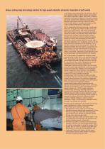
Unique cutting edge technology solution for high-speed automatic ultrasonic inspection of girth welds In the newly constructed gas and oil off-shore and onshore pipelines pipes are girth-welded automatically then rapidly inspected, coated, and buried. Detection, evaluation, and repair of defects in the welds must be very quick in order not to affect the construction cycle therefore high-speed automatic ultrasonic testing (AUT) of girth welds is incredibly demanded as sole codes accepted alternative to radiography AUT is implemented through scanning of weld along fusion line using several...
Open the catalog to page 2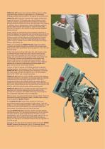
ISONIC PA AUT system from Sonotron NDT represents cutting edge technology solution for high-speed AUT of girth welds bringing practical implementation to the highest convenience level ISONIC PA AUT instrument is packed into rugged portable light weight (6.8 kg only) IP 67sealed case, which is fitted onto the scanner’s chassis; regular remote PC connected to instrument through Ethernet provides full control, data acquisition and imaging in real time, thus no big expensive, heavy vulnerable umbilical – just thin light armoured tube carries DC wires and LAN cable, which are connected to the...
Open the catalog to page 3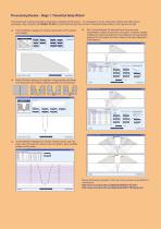
Pre-scanning Routine – Stage 1: Theoretical Setup Wizard Theoretical rays tracing procedure is required for operating of PA probes – it is necessary to cover weld bevel surface and weld volume completely. Ray tracing for the ISONIC PA AUT is performed through very intuitive Theoretical Setup Wizard, which guides through: Probe Definition dialogue for entering parameters of PA probes and wedges Ray Tracing dialogue for determining of zone-by-zone insonification scheme (pulse echo or tandem; incidence angles; emitting and receiving aperture; focal distance) and appropriate positions for PA...
Open the catalog to page 4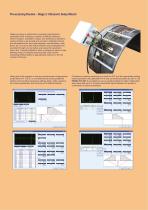
Pre-scanning Routine – Stage 2: Ultrasonic Setup Wizard Ultrasonic setup is performed on specially manufactured calibration block including a number of artificial reflectors, which’s location, orientation, shape, and dimensions represent variety of flaws to be sensed and recorded. Calibration blocks are manufactured for each pipe diameter, wall thickness, weld bevel, etc. by such a way that all defects may be detected and recorded through one revolution scan along the hypothetic fusion line. Typically calibration block is shaped as piece of pipe allowing setup of complete scanning stuff;...
Open the catalog to page 5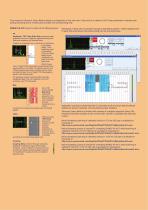
Final screen of Ultrasonic Setup Wizard relates to configuration of the strip chart. Strip chart is a method of AUT data presentation whereas each pulsing-receiving shot is continuously recorded into corresponding strip ISONIC PA AUT may form strips of the following types: Reshaping of Strip Chart is possible through manipulating position / lateral displacement of each strip according to the probes fitting into the scanning frame: PE Amplitude / TOF Pulse Echo Strip represents peak amplitude and time of flight for signals matching with Gate and exceeding it’s threshold level Position of...
Open the catalog to page 6
Scanning and Postprocessing Movies illustrating scanning of girth weld on site are available for download at: http://www.sonotronndt.com/RepInfo/IPAAUT/IPAUT_70MM_SEC.wmv - for 273 mm OD pipe http://www.sonotronndt.com/RepInfo/IPAAUT/OD1219.wmv - for 1219 mm OD pipe Whilst scanning the raw A-Scan data obtained by PA, conventional, and TOFD probes is transferred to remote PC along with corresponding position encoder data. Remote PC provides raw data recording and forms strip chart in real time. Whilst scanning operator may monitor live AScans for every strip. Inspection results file...
Open the catalog to page 7
Up to 512 channels for connection of phased array probes Up to 64 channels for connection of conventional probes for pulse echo and TOFD inspection Parallel A/D conversion and on-the-fly digital phasing and superimposing of PA elements signals, no multiplexing involved Free setting of emitting and receiving aperture accumulating up to 512 elements each Controlled by remote PC through Ethernet, multiple units operation possible Easy-to-follow ray tracing, calibration, and strip chart forming wizard Real time strip chart recording and presentation with complete capturing of raw data A-Scans...
Open the catalog to page 8All Sonotron NDT catalogs and technical brochures
-
 ISONIC 2009
12 Pages
-
 ISONIC 2010
8 Pages
-
 ISONIC_AUT_16_32
4 Pages
-
 ISONIC_utPod_A4_HR
8 Pages
-
 ISONIC 2005
6 Pages
-
 ISONIC 2006
12 Pages
-
 ISONIC 2007
8 Pages
-
 ISONIC 2008
12 Pages
-
 ISONIC PA AUT 16/32
4 Pages