
Catalog excerpts
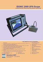
Portable Ultrasonic Phased Array Flaw Detector and Recorder Phased Array ► 64:64 phased array electronics - independently adjustable emitting and receiving aperture, parallel firing, AID conversion, and on-the-fly real time digital phasing ► Phased array pulser receiver with image guided ray tracing ► True-To-Geometry / regular B-Scan and Sector Scan (S-Scan) with all-codes-compliant A-Scan evaluation ► Unique Tandem-B-Scan for the detection of planar vertically oriented defects ► Built-in automatic coupling monitor and lamination checker for wedged probes ► Multi-group / dual side scanning and imaging with use of one probe ► Encoded / time-based line scanning with Top (C-Scan), Side, End Mapping and 3D Viewing ► Automatic generating of editable defects list ► Independent gain per focal law adjustment: pure angle gain compensation for S-Scan, etc ► Processing of diffracted and mode converted signals for defects sizing and pattern recognition ► Operating matrix-array probes with real time three-dimensional imaging (3D-Scan) * Powerful off-line data analysis toolkit * Intuitive User Interface * Light rugged case * Sealed keyboard and mouse * Large 8.5" bright touch screen ► Single / dual modes of pulsing/receiving ► True-to-Geometry flaw detection B- Scan - straight / angle beam probes ► Strip Chart and Stripped C-Scan ► Parallel or sequential pulsing/receiving * Remote control - UT over IP * Built-in encoder port 4, Pekeris str., Rabin Science Park, Rehovot, 76702, Israel
Open the catalog to page 1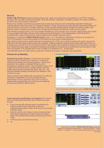
General ISONIC 2009 UPA Scope uniquely combines phased array, single- and multi-channel conventional UT, and TOFD modalities providing 100% raw data recording and imaging. Along with portability, lightweight, and battery operation this makes it suitable for all kinds of every-day ultrasonic inspections Phased array modality is performed by powerful 64:64 phased array electronics with independently adjustable emitting and receiving aperture, each may consist of 1 through 64 elements. Groups of phased array probe elements composing emitting and receiving aperture may be fully or partially...
Open the catalog to page 2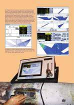
Weld inspection is the typical application benefited through use of True-to-Geometry imaging: upon defining geometry and entering dimensions operator is provided with intuitive ray tracing dialogue indicating actual coverage of the weld for the desired probe position and incidence angle steering range followed by live cross-sectional view either S-Scan or B-Scan with true-to-location defects indication. To ensure detection of variously oriented defects several S-Scan and B- Scan insonifications may be performed simultaneously with use of the same probe providing multi-group cross-sectional...
Open the catalog to page 4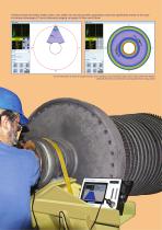
Testing of solid and hollow shafts, axles, rods, billets, etc are among other applications improved significantly thanks to the easy- to-interpret advantage of True-to-Geometry imaging vs regular S-Scan and B-Scan True-to-Geometry S-Scan for single location and complete cross sectional image of the hollow shaft with defects obtained after full circumference scanning with linear array probe
Open the catalog to page 5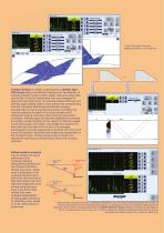
True-to-Geometry S-Scan for longitudinal weld (1) and nozzle (2) Tandem B-Scan is another unique feature of ISONIC 2009 UPA Scope being most effective technique for the detection of vertically situated cracks in welds, plates, tube and vessel walls, and the like. It may be implemented with use of wedged 64elements linear array probe. On entering material thickness and defining a grid dividing object’s cross section into corresponding cells the instrument determines insonification strategy automatically by such a way that focal points of emitting and receiving aperture do match in the center...
Open the catalog to page 6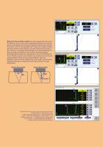
Sizing of near surface cracks may be implemented with use of 64-elements linear array probe. Separated emitting and receiving aperture producing and receiving longitudinal wave have common focal point, which is manipulated over vertical line between bottom and near surface of the material. For each focal law time base of the A-Scan is re-arranged automatically to provide appearance of every possible tip diffraction echo at 50% horizontal position. Recorded signal heights are represented on the Tip Diffraction BScan. Placing mouse cursor (marker) over desired cell reproduces corresponding...
Open the catalog to page 7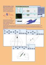
Scan), Side, and End Projection Views is performed through line scanning with linear array probe either encoded or time-based at rectangle to the elements count direction. It is applicable for all types For line scanning every cross sectional view is recorded along with complete sequence of raw data A- Scans it is composed of. C-Scan image is switcheable between distance (thickness or defects depth) Powerful off-line data analysis toolkit includes playing back cross sectional views and A-Scans, gain manipulation in ±6dB range for all recorded A-Scans followed by corresponding image update,...
Open the catalog to page 8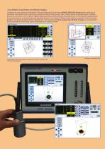
Use of Matrix Array Probes and 3D-Scan Imaging In addition to cross sectional insonification (2D) and imaging with linear arrays ISONIC 2009 UPA Scope allows performing of volumetric insonification (3D); matrix array probes are used for that purpose. Use of matrix arrays is possible thanks to parallel firing, A/D conversion, and ”on-the-fly” digital phasing provided by 64:64 phased array electronics. At the calibration stage phased array pulser receiver is controlled through operating surface of conventional ultrasonic flaw detector supported by 3D ray-tracing graphics. 3D region of...
Open the catalog to page 9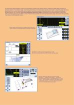
For shear wave weld inspection matrix array should be coupled to the wedge, which's contact face width allows swiveling of ultrasonic beam in the desired range. On entering dimensions of the weld, probe position, and limits for swiveling angle scanning along fusion line may be implemented without typical mechanical skewing of the probe with no risk of missing transversally situated defects. The innovative live true-to-geometry 3D-Scan S image is provided for every lateral position of the probe; 100% raw data capturing is provided so every A-Scan may be played back at the postprocessing...
Open the catalog to page 10All Sonotron NDT catalogs and technical brochures
-
 ISONIC 2010
8 Pages
-
 ISONIC_AUT_16_32
4 Pages
-
 ISONIC_PA_AUT
8 Pages
-
 ISONIC_utPod_A4_HR
8 Pages
-
 ISONIC 2005
6 Pages
-
 ISONIC 2006
12 Pages
-
 ISONIC 2007
8 Pages
-
 ISONIC 2008
12 Pages
-
 ISONIC PA AUT 16/32
4 Pages