Technical Documentation waterfan HEATER
1 /14Pages

Technical Documentation waterfan HEATER
1 /14Pages
Catalog excerpts

Technical Documentation waterfan HEATER v201905 OPERATION AND MAINTENANCE DOCUMENTATION SONNIGER Polska Sp. z o.o. Sp.K. ul. Śląska 35/37, 81-310 Gdynia, Poland, tel. + 48 58 785 34 80, www.sonniger.com 1. INTRODUCTION Rejonowy Gdańsk-Północ, VIII Wydział Gospodarczy Krajowego Rejestru Sądowego, KRS 0000504509, Sąd NIP 586 227 35 14,Regon 22154369 kapitał zakładowy: 1.655.
Open the catalog to page 1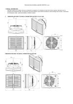
Technical Documentation waterfan HEATER v201905 1.OVERALL INFORMATION HEATER heating and ventilation devices are designed to be applied in the buildings of small and medium capacity, especially such as: production and warehouse halls, car showrooms and service stations, sports halls and stadiums, sacral buildings and churches, retail stores and wholesales outlets, agricultural facilities, exhibition surfaces. DIMENSION AND BASIC TECHNICAL PARAMETERS HEATER R1, R2, R3, MIX DIMENSION AND BASIC TECHNICAL PARAMETERS HEATER ONE
Open the catalog to page 2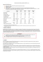
Elements of HEATER devices : IB Casing made of highly resistant EPP (expended polyprophylene) material Bl Regulated air-conduits Bl 3 step axial fan 450 mm dimension; fan is protected from direct access to revolving elements with safety netting Bl Heat exchanger - (Cu/AL) made of copper tubes placed in an aluminum lamellar exchanger /block with stub connection %”.Stub connections are equipped with air-release valves and heat outlet vent. HEATER HEATER parametry No of unit rows Max air output Heat output range Air temperature increase* Max working pressure max airflow range Diameter of connection...
Open the catalog to page 3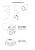
Technical Documentation waterfan HEATER v201905 Mounting bracket to the heater The bracket set consist of: a holder, two sleeves, two M8 screws and washers. In order to mount the bracket, drill two Ø1213mm holes in places visibly marked on the casing. Insert sleeves into drilled holes and place the bracket in. The included holder must be screwed with M8 screws with washers. Installation of mounting pins To mount the heater to the ceiling, use M8 mounting pins. Drill two Ø8-9mm holes in places visibly marked on the casing. Mounting pins may be screwed into the frame not deeper than 20 mm. .
Open the catalog to page 4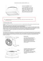
Technical Documentation waterfan HEATER v201905 Assembly of HEATERMIX air mixer To mount HEATERMIX air mixer to the ceiling, use M8 mounting pins. Drill two Ø8-9mm holes in places visibly marked on the casing. Mounting pins may be screwed into the frame of a heat exchanger to the maximum depth of 20mm. Mounting pins and connecting elements are not included with the unit. NOTICE ! To sustain proper functioning of the device keep a safe distance– 200mm from its sides and 300 mm from its backside (from the fan) 5. ELECTRICAL INSTALLATION The electrical installation and connection to power supply...
Open the catalog to page 5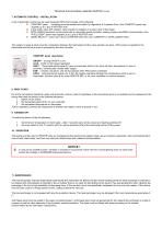
Technical Documentation waterfan HEATER v201905 7. AUTOMATIC CONTROL – INSTALLATION A set of automatic control may be used (powered 230V) that consists of the following: COMFORT panel – including room thermostat and switch for regulation of 3 speeds of fan. One COMFORT panel may regulate up to 3 pcs of HEATER units 2-way water valve with actuator; valve should be installed on a return stub of the heater INTELLIGENT electronic control panel with an automatic speed controller, weekly program and BMS communication. One INTELLIGENT panel may regulate up to 2 pcs of HEATER units Splitter MULTI 6 -...
Open the catalog to page 6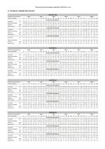
inlet/outlet water temperature 50/40 60/40
Open the catalog to page 7
Technical Documentation waterfan HEATER v201905 13. ELECTRICAL CONNECTION DIAGRAMS 1. Connecting HEATER with no automatic control * The unit set does not consist of: a master switch, a fuse, a feeding cable Fan wiring description U1 high speed – brown U2 middle speed – grey U3 low speed – red N neutral – blue PE protection - yellow/green 2. Connecting a few HEATER units with COMFORT panel, valves and actuators. * The unit set does not consist of: a master switch, a fuse, a feeding cable * One COMFORT panel may regulate up to 3 pcs of HEATER units HEAT - thermostat sends signal for valve/actuator...
Open the catalog to page 8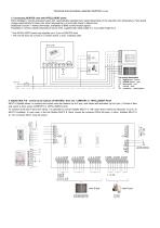
Technical Documentation waterfan HEATER v201905 3. Connecting HEATER units with INTELLIGENT panel. Panel Intelligent controls actuators/valves and automatically regulates fans’ speed depending on the required room temperature. Fans speed changs automatically for lower rate, when temperature in a room gets closer to desired one. Additional functions – weekly thermostat, availability of BMS communication signals Possibility to connect outside temperature sensor NTC, supplied with cable lenght 5 m, max cable length 20 m. * One INTELLIGENT panel may regulate up to 2 pcs of HEATER units * The unit...
Open the catalog to page 9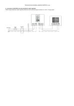
Technical Documentation waterfan HEATER v201905 5. Connection of HEATER unit with transformer speed regulator. * When using transformer speed regulator please use only maximum speed connector on a fan - U1 high speed
Open the catalog to page 10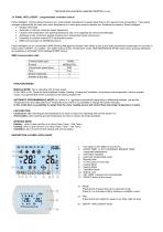
14. PANEL INTELLIGENT - programmable controller manual Panel Intelligent controls actuators/valves and automatically regulates fan's speed depending on the required room temperature. Fans speed changes automatically for lower rate, when temperature in a room gets closer to desired one. Additional functions of Panel Intelligent: • Weekly thermostat • Automatic or manual 3-step fan speed adjustment. • Control room temperature ( by opening/closing the vale, or by adjusting air volume automatically). • Antifreeze mode- protection against dropping room temperature below critical level. • Possibility...
Open the catalog to page 11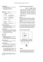
SETTINGS MENU • When Panel Intelligent is switched off, press and hold MODE for 3 seconds. • To change option use MODE button. • To change value use +/- buttons. 1 -6 available time zones S1 : Status; N: Setpoint Remarks During setting, displays can be set while they are flickering. When the beginning time is flickering, it is able to be set (10 mins each step) via scrolling +/- buttons. The time setting is the beginning of current time zone, also the end time of last time zone When ON/OFF is flickering, it is able to be set via scrolling +/ -buttons. When status in ON, thermostat will run according...
Open the catalog to page 12All Sonniger catalogs and technical brochures
 No. 1 in Europe-HEATER ONE
12 Pages
 LUFTERHITZER
4 Pages
 GUARDPRO
15 Pages
 GUARD
GUARD19 Pages
- Air curtain
- Horizontal air curtain
- Ambient air curtain
- Air heater unit
- Air curtain with electric heating
- Industrial air heater unit
- Wall-mounted air heater unit
- Hot air curtain
- Air curtain with water heating
- Hot water air heater unit
- Vertical air curtain
- Industrial door air curtain
- Cold air curtain
- Wall-mounted air curtain