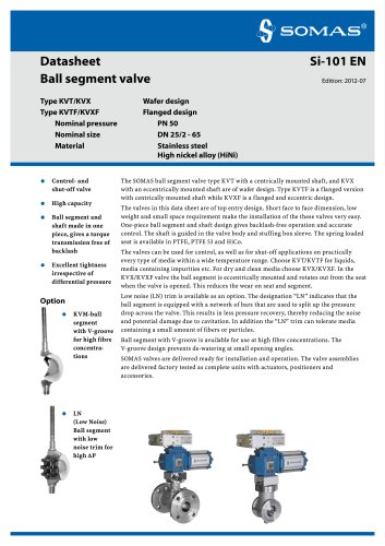
Catalog excerpts
General information SP400/405 2Function SP400/405 2 General information SPE400/405 3 Function SPE400/405 3 Installation 4 Zero-point and range adjustment 4 Maintenance 5 Replacement of cam disc 6 Table cam discs 6 Change-over function 7 Spare parts list SP400/405 8 Detailed drawing SP400/405 9 Spare parts list I/P-converter E400 10 Detailed drawing I/P-converter E400 11 Technical speci cation 12Material speci cation 12 >
Open the catalog to page 1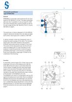
General SP400/405 is a pneumatic valve positioner for an input signal of 20100 kPa (3֖15 psi). The easily exchange- able cam disc is available in various types for diffe- rent valve characteristics, opening angles, as well as for split range 2060 or 60֖100 kPa (39 or 9֖15 psi). See table on page 6.The positioner is mainly designed to fit the SOMAS range of valves and actuators but can easily be adap- ted to other valve types with a rotation of 60Ж90.A yellow indicator under the transparent cover in-dicates the opening angle of the valve. The indicator shows open valve when parallel to the...
Open the catalog to page 2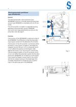
General The electropneumatic valve positioner type SPE400/405 is built on a concept where the pneumatic version type SP400/405 is completed with an I/P-con- verter.This I/P-converter is located in a separate housing, attached to the pneumatic version SP400/405. Zero-point and range adjustments are done on the pneumatic side. See page 4. > Function The function of the SPE400/405 is identical to that of the SP400/405. The difference is that the pneumatic input signal comes from the attached I/P-converter.The function of the I/P-converter is as follows: When the electric input signal increases...
Open the catalog to page 3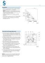
Make sure the positioner has not been damaged during transportation or installation.֖ NOTE! The supply air must be clean and dry instru- ment air and have a constant pressure within the range of 48 bar (60֖120 psi). Connect the supply air to connection marked ֓SUPPLY.Ԗ All pneumatic connections are G 1/4, female thread. Connect air signal to actuator at connections marked ֓A and ԓB. > 1. At initial position (closed valve), make sure that there is a clearance of about 0.5 mm between the ball bearing (16) and the cam disc (32) at an input signal of 20 kPa (3 psi). 2. To adjust the basic...
Open the catalog to page 4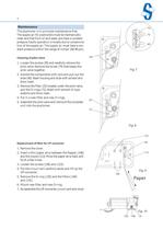
The positioner is in principle maintenance-free.The supply air for positioners must be mechanically clean and free from oil and water and have a constant pressure. Faulty operation is mostly due to contamina- tion of the supply air. The supply air must have a con- stant pressure within the range of 4-6 bar (60-90 psi). > Cleaning of pilot valve 1. Loosen the screws (39) and carefully remove the pilot valve. Remove the screw (74) that keeps the pilot valve together.2. Handle the components with care and pull out the slide (40). Wash housing and slide with solvent and blow clean.3. Remove the...
Open the catalog to page 5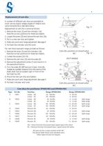
6 Replacement of cam disc > A number of different cam discs are available to cover various signal ranges, angles of rotation and valve characteristics. See table below.Replacement of cam disc is done as follows: 1. Remove the cover (5) and the indicator (10). Note the correct positions for these two details.2. Loosen the screw (33) and remove the cam disc (32). 3. Put in a new cam disc and tighten. 4. Make zero-point and range adjustment. See page 4. 5. Put back the indicator and the cover.For cam discs type split range, proceed as follows:1. Remove the cover (5) and the indicator (10)....
Open the catalog to page 6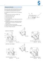
7 Change-over function > If not particularly specified, the positioner is moun-ted to the actuator and connected for direct action. I.e. increased input signal opens the valve, AO.For change-over to reverse function, AC, proceed as follows:1. Remove the cover (5) and the indicator (10). 2. Loosen the screws (33 + 73). 3. Remove the cam disc (32). 4. Lift up the plate (8). 5. Turn the plate (8) and put it back according to the figures below.6. Re-assemble the cam disc in upside down position. (The cam disc will now have a rising slope at clock- wise rotation).7. Change connections to the...
Open the catalog to page 7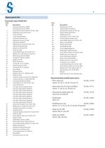
61a Key, SP400, SS 2350 61b Driver, SP405, SS2331-43 62 Diaphragm, Hypalone CSM1 63 Screw, M5x10, Steel, Z.Pl., SS-ISO 1580 64 Washer, dia. 5x16, Steel, Z.Pl. 66 Screw, M5x6, Brass, Nickel Pl. 68 Rivet, 2.5x9, Steel, DIN 660 69 Washer, 8.4x16x1.5, Steel, Z.Pl. 72 O-ring, dia. 4.1x1.6, Nitrile 73 Screw, M5x8, Steel, Z.Pl., SS-ISO 1580 74 Screw, M3x10, Steel, Z.Pl., SS-ISO 2009 75 Washer, dia. 5.3x10, Nylon, DIN 125 76 Nut, M4, Steel, Z.Pl., SS-ISO 4032 77 Silencer 78 Elastic pin, dia. 2.5x10, Stainless steel > Item No. Description 1 Housing, Aluminium, SP400 Housing, Aluminium, SP405 2...
Open the catalog to page 8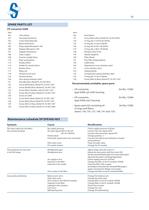
Item No. Description 101 Housing, Aluminium 102 Cover, Polycarbonate 103 Block, Aluminium 104 Relay angle, Wacoperm 100 106 Flapper, Wacoperm 100 107 Adapter, Aluminium 108 Tube, Copper 109 Counter weight, Brass 110 Plate spring, Brass 113 Nozzle, Delrin 114 Holder for nozzle, Delrin 115 Bracket, Brass 117 Relay coil 118 Printed circuit card 119 Terminal board 120 Zero spring, Stainless steel 121 Nut, M6, Brass, Nickel Pl., SS-ISO 4032 122 Screw, M4x8, Brass, Nickel Pl., SS-ISO 1207 123 Screw, M3x40, Brass, Nickel Pl., SS-ISO 1207 124 Screw, M3x3, Stainless steel, SS-ISO 1207 125 Screw,...
Open the catalog to page 10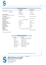
Control signal : Standard 20-100 kPa 4 - 20 mA Split range 20-60 kPa 4 - 12 mA 60-100 kPa 12 - 20 mA Air consumption : max 10 Nl/min. max 15 Nl/min. (at balance and 6 bar supply pressure) Air capacity : 450 Nl/min. approx. 450 Nl/min. approx. (at 6 bar supply pressure) Max voltage drop : ח 8.6 V at 20mA Cam discs : See table, page 6 Connections : G 1/4 (BSP) G 1/4Ԕ (BSP) Supply pressure : 4-8 bar 4-8 bar Ambient temperature : -40 to +100аC -40 to +100аC Hysteresis : 0.5 % 1 ѱ 0.5 % Repeatability : < 0.5 % 1 < 0.5 % ٹ Input resistance : ח 430 Ohm Weight : 1.5 kg 2.3 kg Supply air : Dry and...
Open the catalog to page 12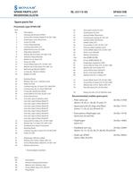
61a Key, SP400, SS 2350 61b Driver, SP405, SS2331-43 62 Diaphragm, Hypalone CSM1 63 Screw, M5x10, Steel, Z.Pl., SS-ISO 1580 64 Washer, dia. 5x16, Steel, Z.Pl. 66 Screw, M5x6, Brass, Nickel Pl. 68 Rivet, 2.5x9, Steel, DIN 660 69 Washer, 8.4x16x1.5, Steel, Z.Pl. 73 Screw, M5x8, Steel, Z.Pl., SS-ISO 1580 74 Screw, M3x10, Steel, Z.Pl., SS-ISO 2009 75 Washer, dia. 5.3x10, Nylon, DIN 125 76 Nut, M4, Steel, Z.Pl., SS-ISO 4032 78 Elastic pin, dia. 2.5x10, Stainless steel > Item No. Description 1 Housing, Aluminium, SP405 > 1 2 Screw, M5x10, Brass, Nickel Pl. SS-ISO 1580 3 Diaphragm cover, Aluminium...
Open the catalog to page 13All SOMAS catalogs and technical brochures
-
Si-208 EN
12 Pages
-
Ball segment valve
8 Pages
-
Actuators Type A
8 Pages
-
Check valves: BCV/BCVA
4 Pages
-
Ball valves: SKV
12 Pages
-
Si-210
4 Pages
-
Si-206
8 Pages
-
Si-205
8 Pages
-
Si-204
8 Pages
-
Si-203
8 Pages
-
Si-113
8 Pages
-
Si-112
8 Pages
-
Si-101
8 Pages
-
Hand lever - Gear unit
4 Pages
-
3-piece full bore ball valve
4 Pages
-
Butterfly valves: VSS
8 Pages
-
KVTW-D/KVXW-D
8 Pages
-
KVTW-A/KVXW-A
8 Pages
-
KVTF-C/KVXF-C
8 Pages
-
Si-111 EN
4 Pages
-
Si-110 EN
8 Pages
-
Si-109 EN
8 Pages
-
Si-108 EN
4 Pages
-
Si-105 EN
4 Pages
-
Si-103 EN
4 Pages
-
Manual actuators
2 Pages
-
Pneumatic actuator
8 Pages
-
CHECK VALVE
4 Pages
-
Butterfl y valve
8 Pages
-
Ball segment valve
8 Pages


