
Catalog excerpts
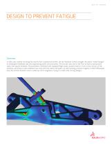
DESIGN TO PREVENT FATIGUE Overview In 1954, two crashes involving the world’s first commercial airliner, the de Havilland Comet, brought the words “metal fatigue” to newspaper headlines and into long-lasting public consciousness. The aircraft, also one of the first to have a pressurized cabin, had square windows. Pressurization combined with repeated flight loads caused cracks to form in the corners of the windows, and those cracks widened over time until the cabins fell apart. As well as being a human tragedy in which 68 people died, the Comet disasters were a wake-up call to engineers trying to create safe, strong designs.
Open the catalog to page 1
Since then, fatigue has been found at the root of failure of many mechanical components such as turbines and other rotating equipment operating under intense, repeated cyclical loads. The primary tool for both understanding and being able to predict and avoid fatigue has proven to be finite element analysis (FEA). What is fatigue? Designers normally consider the most important safety consideration to be the overall strength of the component, assembly, or product. To design for this, engineers want to create a design that will stand up to the probable ultimate load, and add a safety factor...
Open the catalog to page 2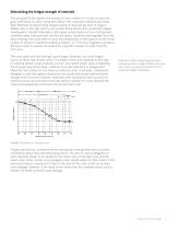
Determining the fatigue strength of materials Two principal factors govern the amount of time it takes for a crack to start and grow sufficiently to cause component failure: the component material and stress field. Methods for determining fatigue testing of materials go back to August Wöhler who, in the 19th century, set up and conducted the first systematic fatigue investigation. Standard laboratory tests apply cyclical loads such as rotating bend, cantilever bend, axial push-pull, and torsion cycles. Scientists and engineers plot the data resulting from such tests to show the relationship...
Open the catalog to page 3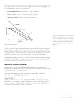
Many service load histories will have a non-zero mean stress. Three mean stress correction methods have been developed to eliminate the burden of having to carry out fatigue tests at different mean stresses: • Goodman method: generally suitable for brittle materials • Gerber method: generally suitable for ductile materials • Soderberg method: generally the most conservative Mean correction methods Companies want and need to reduce weight and material use, and yet still to avoid failures due to fatigue, which even if not fatal, can be very expensive. All of these factors have served to make...
Open the catalog to page 4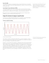
Strain life (EN) This approach provides more detailed analysis of plastic deformation at localized regions, and is good for low cycle fatigue applications. However, some uncertainties in the results exist. Linear Elastic Fracture Mechanics (LEFM) This method assumes that a crack is already present and detected, and predicts crack growth with respect to stress intensity. This can be practical when applied to large structures in conjunction with computer codes and periodic inspection. Physical testing is clearly impractical for every design. In most applications, fatigue safe life design...
Open the catalog to page 5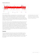
Variable amplitude load: Variable amplitude loading Most components undergo a varying load history in real life conditions, in terms of both amplitude and mean stress. Therefore, a far more general and realistic approach considers variable amplitude loading, in which the stresses, although repetitive over time, have varying amplitude, making it possible to split them into load “blocks.” To solve this type of loading, engineers use a technique called “rainflow counting.” Appendix B, which discusses how to study FEA fatigue results, offers more information on rainflow counting. FEA provides...
Open the catalog to page 6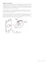
Appendix A: Crack Growth Two physical mechanisms drive the process of fatigue crack growth. Under a cycling load, slip planes in the microstructure of the material grain move back and forth, causing micro extrusions and intrusions on the surface of the component. These are far too small to see—measuring between one and 10 microns in height—but can be considered to be embryonic cracks (Stage I). When the Stage I crack reaches the grain boundary, the mechanism transfers to the adjacent grain. Stage I cracks grow in the direction of the maximum shear, 45 degrees to the direction of loading. At...
Open the catalog to page 7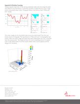
Appendix B: Rainflow Counting Taking a graphic depiction of the varying amplitude loads and extracting the peaks and valleys of the load history, it becomes possible to determine the stress range and its associated mean stress. The graph shows a load history that’s “filled with rain” initially. The stress range and its associated mean stress are determined from the load history shown in the graph. The load history is “filled with rain” in the graphed load history. After the stress range and mean have been determined, the “rain” is drained from the lowest point. The range and mean for each...
Open the catalog to page 8All SOLIDWORKS Europe catalogs and technical brochures
-
SOLIDWORKS PCB CONNECTOR
2 Pages
-
BUSINESS INNOVATION
6 Pages
-
INDUSTRY INNOVATION
3 Pages
-
PROJECT PLANNER
2 Pages
-
SOLIDWORKS CAM
2 Pages
-
SOLIDWORKS Electrical 2017
6 Pages
-
SOLIDWORKS Simulation 2017
6 Pages
-
SOLIDWORKS Premium 2017
6 Pages
-
SOLIDWORKS PREMIUM
8 Pages
-
SOLIDWORKS ELECTRICAL SUITE
6 Pages
-
SOLIDWORKS PDM
4 Pages
-
SOLIDWORKS VISUALIZE
4 Pages
-
SOLIDWORKS COMPOSER 2015
4 Pages
-
SOLIDWORKS ELECTRICAL
4 Pages
-
SW2014 Datasheet Simulation
6 Pages
-
solidworks inspection
3 Pages
-
3DVIA Composer 2013
4 Pages
-
SolidWorks Premium
8 Pages
-
EPDM Data Sheet
4 Pages
-
SOLIDWORKS SIMULATION
6 Pages
-
SolidWorks Plastics
4 Pages
-
3DVIA Composer - Data sheet
2 Pages


