Catalog excerpts

BRIDGING THE WORLDS OF 2D AND 3D CAD DESIGN Overview As manufacturers rapidly transition from 2D to 3D CAD in today’s digital world, designers are demanding 3D to enhance their designs and improve communication. From websites to rapid prototyping, customers, designers, and engineers now depend on the latest 3D modeling tools. In this paper, we highlight the advantages of designing with SolidWorks® 3D CAD software as well as explaining how to leverage your existing 2D CAD data once you have decided to go 3D.
Open the catalog to page 1
Advantages of 3D CAD As you work with 3D CAD software, you will quickly discover that 3D enhances not only the design process, but also communication with your customers and design team. Following are the main advantages of using SolidWorks 3D CAD software: Enhance visualization and communication CAD is all about communicating ideas. We live in a 3D world, so we visualize objects in the same way. When it comes to communicating a design, we naturally prefer a 3D image, model, or animation over a 2D technical drawing. In the 2D world, designers must be able to look at three or four views of a...
Open the catalog to page 2
Rick Morse, owner of Pearce Processing Systems in Gloucester, Massachusetts, says that being able to present his proposals and finished designs in 3D to his customers makes communication much easier than providing them 2D drawings. Morse also makes extensive use of 3D animation. The ability to show his customers a “movie” of the machine in action not only communicates how the machine will function, but also gives him an edge over others who are submitting 2D drawings in the quoting phase. With 3D images and 3D animations potential customers feel more confident in what Morse will be...
Open the catalog to page 3
3D CAD software allows you to thoroughly explore an assembly with explode, unexplode, and hide parts from views capabilities. Eliminate manual updates In 2D, you have to manually update every drawing view whenever a change occurs. Change one part and you not only have to include that change in each of the three drawing views for the part, you must also change every view of every assembly in which that part is used. Rick Morse says he wonders how they ever made a machine in the past in 2D CAD. He spent much of his design time just trying to keep all his drawing views up to date as his...
Open the catalog to page 4
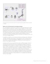
2D drawing views are automatically created from the 3D model and updated whenever the model is changed. Reduce errors with interference and collision checking On a 2D drawing, part interferences are difficult to find, especially when the design becomes large and complicated. In addition, because updates to 2D take so much time, many users often take shortcuts, like changing a dimension on a part without updating the actual size of the model. How many times have you heard that “the drawing is not to scale”? Add to this the fact that multiple designers will be sharing the assembly design...
Open the catalog to page 5
Interferences also result from tolerancing problems. SolidWorks software provides the ability to automatically check maximum and minimum tolerance conditions with its TolAnalyst™ functionality, so you can ensure the tolerances you are applying to your parts are appropriate. It even identifies which tolerances are the largest contributors to the tolerance stack-up problem, thereby saving you time in trying to figure out which tolerances to tighten, or which dimensioning schemes to change. When fit and function errors go down, efficiency goes up, and you reduce time, labor, and material...
Open the catalog to page 6
Reuse existing designs Two unique aspects of SolidWorks software allow you to make easy and extensive reuse of existing designs: associativity and modifiability. As discussed earlier, “associativity” means when you change a design model, the change automatically ripples through to all the other places where that model is used—the drawings, higher level assemblies, and more. By “modifiability” we mean you can change a part by clicking and changing a dimension and all other geometry on that part resizes appropriately and automatically. For example, if you have modeled a fiveinch-long plate...
Open the catalog to page 7
'aflmlimvorKi D-iiB-s-^-ll You can automate the creation of new designs with DriveWorksXpress. Accelerate development cycles with virtual testing and optimization Speeding up a design cycle depends on more factors than simply streamlining the initial part or assembly design. Another major benefit with 3D modeling is the insight it offers through virtual testing, analysis, and optimization, which take many forms. Tiffany appreciates that working in SolidWorks software allows him to apply motion to the parts of an assembly and quickly evaluate many different designs against operational...
Open the catalog to page 8
In addition the motion simulation capability found in SolidWorks software allows you to evaluate the effects of different motor performance curves, friction, springs, gravity, and other physical characteristics of a design. So rather than just running an animation of the machine in motion, you can simulate what really is happening in your design. The motion simulation automatically calculates forces on critical components, like bearings, bushings, and linkages. This information is then used to calculate part strengths, deflection, fatigue, and safety factors. Thermal, vibration, and flow...
Open the catalog to page 9
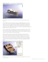
With SolidWorks software you can automatically dimension 3D models according to industry standards. With SolidWorks software, design-for-manufacturing (DFM) becomes more than a catch phrase. Built-in manufacturing intelligence (called DFMXpress) directs the software to check for features that are expensive or impossible to manufacture. These features are highlighted, and the user is provided an interactive list of the problems uncovered. Communication between manufacturing and engineering is also greatly improved through the use of 3D. There is a wide range of 3D digitizing and inspection...
Open the catalog to page 10
Create bills of materials and manage data smoothly Working with an associative 3D CAD system also guarantees an accurate and current bill of materials (BOM). The BOM is always accurate because it automatically updates with changes you make to parts and assemblies. Data management is always critical to the product development process. Designs often go through several stages of development, such as concept, detailed engineering design, assembly and test, and final release to production. Controlling data is especially important when you consider all the personnel that are required to develop...
Open the catalog to page 11All SOLIDWORKS Europe catalogs and technical brochures
-
SOLIDWORKS PCB CONNECTOR
2 Pages
-
BUSINESS INNOVATION
6 Pages
-
INDUSTRY INNOVATION
3 Pages
-
PROJECT PLANNER
2 Pages
-
SOLIDWORKS CAM
2 Pages
-
SOLIDWORKS Electrical 2017
6 Pages
-
SOLIDWORKS Simulation 2017
6 Pages
-
SOLIDWORKS Premium 2017
6 Pages
-
SOLIDWORKS PREMIUM
8 Pages
-
SOLIDWORKS ELECTRICAL SUITE
6 Pages
-
SOLIDWORKS PDM
4 Pages
-
SOLIDWORKS VISUALIZE
4 Pages
-
SOLIDWORKS COMPOSER 2015
4 Pages
-
SOLIDWORKS ELECTRICAL
4 Pages
-
SW2014 Datasheet Simulation
6 Pages
-
solidworks inspection
3 Pages
-
3DVIA Composer 2013
4 Pages
-
SolidWorks Premium
8 Pages
-
DESIGN TO PREVENT FATIGUE
8 Pages
-
EPDM Data Sheet
4 Pages
-
SOLIDWORKS SIMULATION
6 Pages
-
SolidWorks Plastics
4 Pages
-
3DVIA Composer - Data sheet
2 Pages


