
- Catalogs
- Solidat Applied Technologies Ltd.
- Gauger420 - User Manual


Gauger420 - User Manual

Gauger420 - User Manual
- Power On Faults: If the Gauger420 does not power on, check the power supply ratings and electrical connections. If it powers on but does not measure, ensure it is not powered via USB.
- Ultrasonic Related Faults: For constant ECHO SEARCH status, ensure the target is within the specified range, the sensor is correctly aimed, and the sensor face is clean. For incorrect level measurements, verify distance measurement and settings. If the level measurement displays Full level continuously, clear disturbances and adjust NBD if using an extension pipe.
Catalog excerpts

You Can Measure the Solid Benefits…
Open the catalog to page 1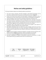
Notices and safety guidelines This manual is delivered subject to the following conditions and restrictions: The manual contains proprietary information belonging to Solid Applied Technologies Ltd. The information is published solely for the purpose of assisting authorized users of Gauger420. No part of this manual may be used for any other purpose, or disclosed to any person or firm, or reproduced by any means, without the prior written permission of Solid Applied Technologies Ltd. The text and graphics in this manual are for the purpose of illustration and reference only. Information included...
Open the catalog to page 2
I. Introduction I.1. Description Gauger420 is a mono-block, 2-wire, ultrasonic level meter with integrated 4-20 current loop and USB interface for configuration and firmware upgrade. Optional items include display, HART protocol and external temperature sensor. Gauger420 measures distance. Targets may be liquid or solids. Measurement is continuous and does not require contact with the target. The system can accurately measure steady or agitated target surfaces. The system can also rapidly track filling and emptying of vessels. The measurement distance spans 15 cm to 8 meters for Gauger420 / 75...
Open the catalog to page 7
Figure 2 – Gauger420 dimensions for 75 KHz version For Gauger420 / 50 KHz, sensor threads are 2”BSP/NPT.
Open the catalog to page 9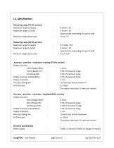
Measuring range (75 KHz version) Maximum range for liquids Maximum range for Solids Minimum range (dead zone) Measuring range (50 KHz version) Maximum range for liquids Maximum range for Solids Minimum range (dead zone) Approximate, depending on type of solid Approximate, depending on type of solid Accuracy - precision - resolution -tracking (75 KHz version) Display Accuracy Display Precision (repeatability) - 0.2% of measured range Process tracking rate - 10 meter per minute maximum For process rates up to 5 meter per minute Accuracy - precision - resolution -tracking (50 KHz version) Display...
Open the catalog to page 10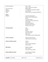
Current consumption 4.0mA – 20mA 3.6mA – 22mA for error settings 950Ω at 33VDC For configuration and firmware upgrade For monitoring 64X128 Graphic LCD, viewing size 50X25mm2 Loop current circuit USB port RS485 port Display Reports Displayed Level and percentage level Distance and percentage distance Volume Flow (open channel) Temperature (internal and external) Echo strength Global operating hours Resettable operating hours Ultrasonic status reports Level Distance Volume Flow (open channel) Open Channel Flow Fixed current 4mA and 20mA may be set independently Target closer than Full level Target...
Open the catalog to page 11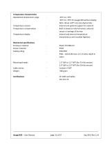
Temperature characteristics Operational temperature range Temperature sensors Temperature compensation Temperature display Mechanical specifications Enclosure material Sensor material Sealing rating -20°C to +70°C -30°C to +70°C for Gauger420 without display Note: above +60°C accuracy depreciates Internal and optional support for external Built-in based on internal sensor, external sensor or average of the two Internal and external temperature Instantaneous and recorded high/low Plastic PC/ABS+UV PVDF IP65/IP67 IP68 – tested 96 hours at 1.8 meter depth in water Mounting threads Cable entries...
Open the catalog to page 12
I.5. HOW TO USE THIS USER MANUAL At this stage… First thing If you are not familiar with Level measurement terms If you are ready to power up the Gauger If you want to quickly configure the Gauger If you want to know all about Gauger configurations If you are about to install in the field If you are unsure about any term or concept Do this… Read the description section in this introduction chapter. Also review the safety guidelines right at the beginning of this user manual. Review the section: Application dimensions and constraints in the reference guide chapter. Review the sections: electrical...
Open the catalog to page 13
II. Physical and electrical installation guidelines This chapter is a list of guidelines for proper physical installation of Gauger420 on tanks including electrical connections. The final section is a short and concise list of instructions – the “must-be pamphlet”. Always ensure that Gauger420 is installed in an area that meets the stated ratings of the product including temperature and technical specifications Gauger systems are installed above the target (e.g. water, fuel) being measured and should not make contact with the target at any time. Typically, the systems are installed on top of...
Open the catalog to page 14
For solids in silos, Gauger420 should be aimed towards the center of the silo’s base. The sensor should be displaced from the center of the tank and oriented perpendicular to the solids surface when tank is at full state. Figure 4 - Silo (left) and liquid (right) examples Proper physical installation is accompanied by software setup. Setup includes defining parameters such as tank height and may include additional parameters such as NBD, FBD, False echo scan and more. For additional information read the section in the reference guide: “Application dimensions and constraints”. II.2. Tank fitting...
Open the catalog to page 15
threads. Preferably, tighten by hand only. If you do use a wrench, grip Gauger420 at the wrench grip surfaces only (see figure Gauger420 parts) and exert light force. II.3. Dead zone See reference guide: “Application dimensions and constraints”. A gap must be kept between the face of sensor and the topmost level of the target. This gap must be at least the size of the specified “dead zone”. If the target level passes the dead zone, measurements may be unpredictable. Therefore, it is recommended to keep a margin gap between the expected topmost level and the dead zone border. Where the topmost...
Open the catalog to page 16
Pipe should be exactly perpendicular to the surface of the target Sensor must be located at the center of the pipe Pipe should have a smooth interior surface The hole in the flange or tank should have a smooth edge and welding spots must be avoided Preferably, the pipe should be made of plastic Figure 7 – Possible extension pipe fittings II.5. Temperature considerations and temperature sensors See also reference guide: “Temperature sensors, units and display”. When using an external temperature sensor, place the sensor at a location that best represents temperature of the air between the sensor...
Open the catalog to page 17All Solidat Applied Technologies Ltd. catalogs and technical brochures
 MonoScan Data Sheet
2 Pages
 SMARTSCAN 50
2 Pages
 GAUGER 485
2 Pages
 GAUGER GSM
2 Pages
 GaugerGSM / 485 - User Manual
94 Pages
 Complete_Product_line_Brochure
13 Pages
 Diesel Tank Monitoring Solution
12 Pages
 Gauger Line Brochure
10 Pages
 Sewer monitoring system
1 Page
 OEM options for GaugerGSM
3 Pages
 GaugerGSM - product highlights
13 Pages
 GaugerGSM - Highlights
11 Pages
 Wireless solution Poster
1 Page
 General purpose Poster
1 Page
 SmartScan User Manual
145 Pages
 MicroScan User Manual
51 Pages
 MonoScan User Manual
88 Pages
 SmartScan
2 Pages
 MicroScan™
2 Pages


- Flowmeter
- Volume flow monitor
- Liquid flow monitor
- Gas flow monitor
- Level probe
- Liquid level sensor
- In-line flow meter
- Analog level sensor
- Level transmitter
- Liquid level transmitter
- Ultrasonic flow monitor
- Digital output level sensor
- Vessel level sensor
- Analog level transmitter
- Liquids level gauge
- Digital output level transmitter
- Storage tank level transmitter
- Explosion-proof level sensor
- Electronic level gauge
- Explosion-proof level transmitter