
- Catalogs
- SOJI ELECTRONICS JSC
- fuel - level sensor

fuel - level sensor

fuel - level sensor
The LIGO Fuel Level Sensor by SOJI Electronics is engineered to measure liquid fuel levels in vehicles and storage tanks, transmitting data via Analog, Frequency, RS232, and RS485 signals. It boasts up to 99.5% accuracy using capacitive sensing technology.
Key Features
- Accuracy up to 99.5%
- Operating voltage range: 7.5 to 75V (LIGO-SP-PRO)
- Isolation voltage: 2500V (LIGO-SP-PRO)
- Adjustable length up to 6000mm
- Automatic length recognition
- Temperature range: -40°C to +85°C
- IP67 waterproof standard
- Interference filter and thermal error compensation
- Quick installation with security seal
General Applications
Suitable for trucks, boats, industrial oil storage tanks, factories, and agricultural machines.
Technical Specifications
Standard lengths up to 6000mm, measuring error of ±0.5%, and various output signals. Operating temperature range is -40°C to +85°C with IP67 waterproof standard. LIGO-SP PRO supports a wide input voltage range and includes an internal temperature sensor.
Overall Dimensions and Description
Constructed with aluminum and stainless steel, the sensor includes a sensing circuit board, gasoline-resistant rubber gasket, and oil filter.
Connector Details
Features a connector with pins for GND, VDC, and output signals, supporting RS232/RS485 and Analog/Frequency connections.
Installation and Configuration
Protected against reverse-polarity and overvoltage, with recommended use of fuses. Configuration software allows setting parameters like output type and sensor calibration.
Connecting Multiple Sensors
Multiple sensors can be connected using a data processor for managing large or complex oil tanks.
Connection Diagrams
Diagrams illustrate connecting multiple sensors with the SUM-DATA processor.
Product and Accessories
Includes standard length sensors (700, 1000, 1500mm), oil filter, gasoline-resistant gasket, anti-vibration spring, 2A fuse, self-drilling screws, rivets, sealing cord, 7m PVC coated signal wire, and installation manual.
Installation
Five-step process: piercing the oil tank, cutting the level indicator, configuring length, installing the indicator, and adjusting the sensor.
Order Codes
Order codes for LIGO-SP and LIGO-SP-PRO sensors with various output options and lengths. Custom lengths available upon request.
Contact Information
Contact SOJI Electronics via their website or offices in Hanoi and Ho Chi Minh, Vietnam. Specifications may change without notice.
Revision History
Second release dated February 20, 2020.
Catalog excerpts
GENERAL APPLICATIONS TECHNICAL SPECIFICATIONS V. OVERALL DIMENSIONS AND DETAILED DESCRIPTION VIII. INSTALLATION LIGO-SP ORDER CODE X. LIGO-SP-PRO ORDER CODE REVISION HISTORY All Rights Reserved. ©2020 SOJI ELECTRONICS DATASHEET LIGO SP SERIES FUEL LEVEL SENSOR|
Open the catalog to page 2
GENERAL INTRODUCTION LIGO Fuel level sensor is produced and developed by SOJI Electronics Limited Company. The device is designed to measure the level of liquid fuel and other non-conductive liquids in vehicle’s tanks and stationary fuel storage, applicable in different fields. The measured values will be transmitted to an external device as an output signal such as: Analog, Frequency, RS232, RS485… in order to connect to an external device. Under particular conditions, the device can reach a high accuracy up to 99.5%. At present, on the market there are several lines of sensor used to measure...
Open the catalog to page 3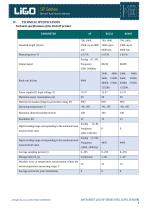
TECHNICAL SPECIFICATIONS Technical specifications of the LIGO-SP product PARAMETER Analog (0…9V), Output signal 2400, Baud rate, bit/sec Power supply (DC input voltage, V) Maximum power consumption, mA Waterproof standard (Ingress protection rating, IP) Maximum allowed humidity level,% Digital reading range corresponding to the minimum level measurement value Digital reading range corresponding to the maximum level measurement value Frequency (500...1500 Hz) Analog (1...9V); Frequency (1000...2000 Hz) Average sampling period, (s) Absolute error in temperature measurement within the entire temperature...
Open the catalog to page 4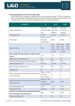
Technical specifications of the LIGO-SP PRO product - LIGO-SP PRO product is designed to applied to devices having wide input voltage (7-75V), the voltage of the internal sensing printed circuit board isolated from outside is 2500V. The internal temperature sensor has a very low error at <0.6°С. The product is designed to operate in extreme environment. Analog (0…9V), Output signal 2400, Baud rate, bit/sec Maximum power consumption, mA Waterproof standard (Ingress protection rating, IP) Maximum allowed humidity level,% Power supply (DC input voltage, V) 2500V internal isolated Digital reading...
Open the catalog to page 5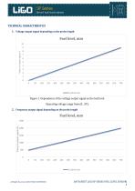
TECHNICAL CHARACTERISTICS 1. Voltage output signal depending on the probe length Value of output sigual, V Figure 1. Dependence of the voltage output signal on the fuel level. Operating voltage range from (0…9V). 2. Frequency output signal depending on the probe length Fuel level, mm Value of output sigual, Hz All Rights Reserved. ©2020 SOJI ELECTRONICS DATASHEET LIGO SP SERIES FUEL LEVEL SENSOR|
Open the catalog to page 6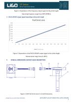
Figure 2. Dependence of the frequency output signal on the probe length. Operating frequency range from (500-2000Hz). 3. RS232/RS485 output signal depending on the probe length Fuel level, mm Value of output sigual, Digital Figure 3. Dependence of the RS232/RS485 output signal on the probe length. Measurement range from (0-4095) V. OVERALL DIMENSIONS AND DETAILED DESCRIPTION Figure 4. LIGO fuel level sensor’s overall dimensions. All Rights Reserved. ©2020 SOJI ELECTRONICS DATASHEET LIGO SP SERIES FUEL LEVEL SENSOR|
Open the catalog to page 7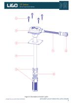
Figure 5: Description of sensor’s parts All Rights Reserved. ©2020 SOJI ELECTRONICS DATASHEET LIGO SP SERIES FUEL LEVEL SENSOR|
Open the catalog to page 8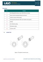
Sensor’s head containing sensing circuit board Gasoline resistant rubber gasket Sensing probe (Aluminium 6061 and stainless steel option) Anti-vibration spring Figure 6. The detail of connector pins All Rights Reserved. ©2020 SOJI ELECTRONICS DATASHEET LIGO SP SERIES FUEL LEVEL SENSOR|
Open the catalog to page 9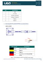
1. Connecting LIGO-SP and LIGO-SP PRO to an external device + RS232/ RS485 WIRE COLOUR Figure 7. Wiring diagram of RS232 and RS485 output signals. All Rights Reserved. ©2020 SOJI ELECTRONICS DATASHEET LIGO SP SERIES FUEL LEVEL SENSOR|
Open the catalog to page 10
All Rights Reserved. ©2020 SOJI ELECTRONICS DATASHEET LIGO SP SERIES FUEL LEVEL SENSOR|
Open the catalog to page 11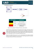
WIRE COLOUR Figure 8. Wiring diagram of Analog and Frequency output signals. LIGO fuel sensor is protected against reverse-polarity and overvoltage. This feature helps to protect circuit boards against incorrect connections and it can withstand a continuous overvoltage condition (up to 50V in LIGO-SP product and 100V in LIGO-SP-PRO product) and shortcircuit. Please avoid connecting sensor to a power supply which is unstable, usually fluctuates, or has a voltage higher than the recommended voltage range above. Using a fuse coupled with one pole (-) or (+) is recommended for over-voltage protection...
Open the catalog to page 12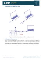
2. Connecting to PC to configure the device Figure 9. Connection diagram of sensor to PC via a configuration tool. 3. Configuration software interface Setting up and managing the appropriate configurations for the sensor is indispensable to properly, stably and accurately operate the device sensor LiGO-AF, as well as usually keep informed about the device’s operating situation, failure (caused by the sensor itself or external factors), and lifespan. All Rights Reserved. ©2020 SOJI ELECTRONICS DATASHEET LIGO SP SERIES FUEL LEVEL SENSOR|
Open the catalog to page 13
Figure 10. Device’s management, setting up and configuration software interface Main parameters: 1. Sensor: Restore password: Restore user password, user will receive an encrypted string which will be sent to SOJI for password decryption Change password: Change user password Load config: Load configurations from sensor to PC. Note: user must load configurations from sensor before changing configurations on PC Save config: Save configurations from PC to sensor Update firmware: Upgrade new firmware for sensor (visit www.sojielectronics.com for the latest firmware version) Set full: Set Full for...
Open the catalog to page 14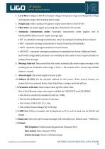
4. Level Max: Configure LIGO SP-AF output voltage or frequency range according to the voltage or frequency range of the tracking device input 5. Output type: Select analog or frequency output (used only for LIGO SP-AF) 6. Filter time: set output signal processing time. Default time 60 seconds. 7. Automatic transmission mode: Automatic transmission mode applied only to RS232/RS485 defines sensor output message type: • Off – no automatic message transmission, sensor is waiting for tracking device request; • HEX - automatic message transmission in binary format (used by default); • ASCII - automatic...
Open the catalog to page 15