- Catalogs
- Soft Robot Tech Co.,Ltd
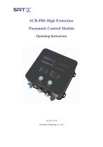
- SCB-PBS High Protection Pneumatic Control Module Operating Instructions V1.0
SCB-PBS High Protection Pneumatic Control Module Operating Instructions V1.0
1 /22Pages

SCB-PBS High Protection Pneumatic Control Module Operating Instructions V1.0
1 /22Pages
Catalog excerpts
Soft Robot Technology Co., Ltd.
Open the catalog to page 1
Safety notes Please read through the safety precautions and user notice before using this product to avoid personal injury or property loss. This product is used with the matched SRT end clamp; do not use it for other purposes. Warning! Operating environment • Do not use this product in an environment with corrosive gas, chemicals, seawater, water or vapor; * Do not use this product in a place with explosive gas and dust; • Do not use this product in a place with vibration or impact; * Do not use this product in a place with heat source and radiation heat; • Take proper protection measures before...
Open the catalog to page 2
4. Operating Instructions of Debugging Software16 5. Common Faults and User Notes18
Open the catalog to page 3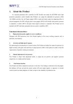
1. About the Product As a specific pneumatic drive controller for SRT flexible end clamp, the SCB-PBS series high protection pneumatic control module (this Product) can output the adjustable air pressure within -60~100kPa and drive the soft finger gripper (SFG) to grip and stretch under the triggering effect of external equipment; the SFG will grip (mini vacuo gripper (MVG) will stretch) when positive pressure is outputted, or stretch (MVG will grip) when negative pressure is outputted. This Product can be matched with SFG and other automation devices easily to establish a SFG. Functional characteristics:...
Open the catalog to page 4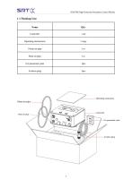
1.1 Packing List Name
Open the catalog to page 5
2. Function Introduction2.1 Display Function Pressure display Display function includes “pressure display” and “indicator” Display the air pressure output from current air outlet in real time; display the set pressure during regulation of positive and negative pressure; alarm information. 2. Indicator: Indicators include: Completion/alarm indication, indication of positive pressure regulation and negative pressure regulation. Completion/alarm indication: When positive or negative pressure is finished on the end gripper, the indicator will be on in green; when air pressure at air inlet fails to...
Open the catalog to page 8
2.2 Manual Control The manual control includes manual switch and regulation knob, as shown in picture below: Manual switch: It consists of pressure trigger and vacuum trigger, to switch the air pressure status of air outlet and reset controller; press the pressure trigger and air outlet will output positive pressure, and drive the end gripper to positive pressure status; press the vacuum trigger and air outlet will output negative pressure, and drive the end gripper to negative pressure status; press the pressure trigger and negative trigger at the same time, the air outlet will output zero pressure...
Open the catalog to page 9
2.3 Input/output The input/output function includes air outlet interface, power interface and I/O interface. Inlet: Applies to air pipe with an outer diameter of 10mm. Outlet: Applies to air pipe with an outer diameter of 8mm. Electrical port: Including power interface, input interface and output interface. The aviation plug is 14-core cable; the mark distribution is as shown in picture below:
Open the catalog to page 10
The relationship between cable and function is shown in table below: Function introduction: 1) DC power supply port: Voltage range is DC24±10%; rated power of power supply is over 50W. 2) Pressure, vacuum and reset trigger port The robot or PLC can control this Product with I/O signal, to output positive pressure, negative pressure, pressure maintaining and zero pressure through this port.
Open the catalog to page 11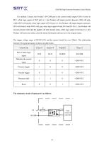
SCB-PBS High Protection Pneumatic Control Module Use method: Connect this Product’s IN-COM port to the control model output COM of robot or PLC; when logic signal of IN-P port is 1, this Product will output positive pressure, SFG will grip, while MVG will stretch; when logic signal of IN-N port is 1, this Product will output negative pressure, SFG will stretch, while MVG will grip; when logic signal of both IN-P and IN-N is 1, this Product will execute pressure relief and the gripper will enter natural status; when logic signal of reset port is 1, this Product will enter reset status, clear the...
Open the catalog to page 12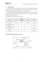
SCB-PBS High Protection Pneumatic Control Module 3) Signal output port: Complete output: When the end gripper finishes pressure or negative regulation according to detection of this Product, the corresponding ports and OUT-COM will be connected, the robot or PLC can check whether the end gripper has finished pressure or negative regulation. Alarm output: When air leakage of end gripper is detected by this Product, the OUT-ERR port and OUT-COM port will be connected, and the robot or PLC will check if the end gripper has air leakage according to the connection conditions. The relationship between...
Open the catalog to page 13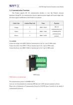
SCB-PBS High Protection Pneumatic Control Module 'V '.V 2.4 Communication Functions This Product supports RS 232 communication interface, to view this Product’s pressure parameters through PC; the communication function supports pressure trigger and vacuum trigger only, but cannot support modification of this Product’s set pressure. Use method: Connect the orange wire (DB9-2 RXD) of electrical port to the No. 2 port of DB9 socket; Connect the yellow wire (DB9-3 TXD) of electrical port to No. 3 port of DB9 socket; Connect the brown wire (DB9-5 GND) of electrical port to No. 5 port of DB9 socket;...
Open the catalog to page 14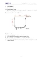
3. Installation 3.1 Installation and Fixing This Product’s mounting holes are arranged at its bottom and the dimensions are as shown in picture below; please use M4*6 bolts during installation. Installation precautions: 1. Install this Product firmly. 2. Do not squeeze the inlet/outlet pipe and cable when fixing this Product. 3. Do not suspend this Product at a high place, to avoid damage due to falling. 4. Make sure this Product is grounded in special operating environment, such as places with strong magnetic interference.
Open the catalog to page 15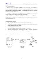
3.2 Circuit Installation Before the circuit is connected, place this Product at a safe position and fix it to avoid falling. Do not place it in sealed box. Make sure the cplOmm air inlet pipe can reach this Product’s air inlet, the cp8mm outlet pipe can connect the end gripper and the 8-6 pneumatic joint is close to the gripper end. The total length should be within 3~5m. Make sure the air pipe is inserted into the quick connector correctly during circuit connection. The air pipe is installed correctly if there’s sense of setback during insertion. Once the air pipe is connected, feed the industrial...
Open the catalog to page 16All Soft Robot Tech Co.,Ltd catalogs and technical brochures


- Analysis software solution
- Measuring machine
- Windows software
- Plastic cap
- Monitoring software solution
- Cylindrical cap
- 3D software solution
- Pneumatic gripper
- Inspection system
- Sorting machine
- 2-jaw gripper
- Automatic sorting system
- Automatic measurement system
- Optical measurement system
- Automatic inspection system
- High-precision measurement system
- Optical sorting system
- Measuring system for industrial applications
- Circular vacuum suction cup
- Parts measurement system