


- Products
- Catalogs
- News & Trends
- Exhibitions
Public distribution catalogue

Public distribution catalogue
SOCOMEC, a French manufacturer since 1965, specializes in public electricity distribution solutions, focusing on securing low voltage (LV) electrical supply, improving safety, and reducing non-technical losses through accurate metering. Their TIPI low voltage feeder pillars are a market leader in France.
SOCOMEC has been innovating for over 90 years, focusing on the availability, control, and safety of low voltage electrical networks. They invest 10% of their turnover in R&D and operate one of Europe's leading independent power testing labs.
- Critical Power: Ensures high-quality power availability for critical applications through uninterruptible power supplies (UPS) and changeover systems.
- Power Control & Safety: Manages power and protects individuals and property with solutions like fuse protection and insulation defect monitoring.
- Solar Power: Provides safety and reliability for photovoltaic (PV) facilities, including energy conversion and storage solutions.
- Energy Efficiency: Improves energy efficiency in buildings by measuring consumption and optimizing tariffs.
SOCOMEC offers personalized support and services to ensure equipment reliability, including assessment, solution implementation, operator training, and preventive maintenance.
All solutions comply with international standards, and SOCOMEC provides multi-field expertise with mechanical, electrical, and IT engineering support for customized solutions.
LV distribution panels are designed for MV/LV substations with 3-pole fuse headers, qualified under EN 61439. They feature panels with 4 or 6 outputs, a SIRCO 1200 A load break switch, and IP2X protection. An integrated solution includes mounted power transformers and auxiliary power units, with options for public lighting control tabs.
The Pierre Siat test laboratory, located in Benfeld, France, is a key quality assurance facility for SOCOMEC. It is recognized by major certification bodies and offers a wide range of tests, including functional, dielectric, mechanical, environmental, and safety tests. The laboratory supports both SOCOMEC products and partners requiring product qualification and certification.
SOCOMEC products comply with the EN 61439 standard, which mandates new verification methods for design and performance. The standard outlines roles and responsibilities for OEMs and assembly manufacturers, with specific requirements for public distribution units.
SOCOMEC offers a range of energy management solutions, including the SUNSYS PCS² power conversion system for energy storage and DIRIS Digiware for multi-circuit measurement and monitoring. These solutions support smart grid innovations by facilitating decentralized electricity production, optimizing grid reinforcement, and reducing environmental impact.
Low voltage grids are evolving to integrate renewable energy and improve grid management. SOCOMEC's solutions, such as the SUNSYS PCS2, enable energy storage and autonomous grid operation. Monitoring solutions like DIRIS Digiware provide real-time analysis and alerts to optimize grid performance.
SOCOMEC has developed advanced energy storage solutions and electrical measurement systems to address the challenges faced by grid operators. These innovations are crucial for integrating decentralized electricity production, ensuring power supply security, and reducing the environmental impact of electrical systems.
Grid operators face challenges such as integrating decentralized electricity production, anticipating failures, and optimizing grid reinforcements. Real-time analysis of electrical flows is necessary for intelligent low voltage (LV) grids. SOCOMEC's solutions, like the DIRIS Digiware, provide multi-circuit measurements and monitoring.
The SUNSYS PCS2 power conversion system is designed for energy storage, enabling the charging and discharging of batteries. These systems convert photovoltaic (PV) energy into usable AC current, supporting grid autonomy and islanding operations. Key functions include frequency regulation, peak shaving, load shifting, and voltage regulation.
SOCOMEC offers plug-and-play solutions for monitoring LV grids in MV/LV substations. These include monitoring transformers, voltage, feeders, and temperature to detect phase unbalances and analyze events in real-time.
The SUNSYS PCS2 system manages the intermittence of renewable energy production by limiting production and stabilizing grid operations. It supports microgrid operations, allowing for autonomous energy supply during grid outages.
SOCOMEC is a partner in the Nice Grid pilot project, which aims to develop a more interactive and flexible power grid. The project integrates decentralized renewable energy, energy storage, and demand response, with objectives to optimize network operations and empower consumers in energy management.
The SUNSYS PCS2 offers modular energy storage solutions from 33 kW to several MW, with high efficiency and flexibility. It supports various battery technologies, including lithium-ion and lead-acid, and provides secure maintenance options.
SOCOMEC's innovations in energy storage and grid monitoring are pivotal for the development of smart grids, enhancing grid stability, and supporting renewable energy integration.
The document provides technical specifications and features of the SUNSYS PCS2 power converters and the DIRIS Digiware measurement and monitoring system. It highlights their applications in energy storage and electrical installations, emphasizing modularity, efficiency, and ease of maintenance.
- Design: Modular conversion solution for energy storage ranging from 33 kW to several MW.
- Input (DC): Battery voltage ranges from 450 to 850 VDC with varying numbers of independent converters.
- Output (AC): Nominal power ranges from 33,300 W to 100,000 W, with a maximum efficiency of up to 98%.
- Environment: Suitable for non-air-conditioned indoor spaces with an operating temperature range of -5°C to +60°C.
- Cooling System: Smart cooling included.
- Functionality: Provides a flexible and easy-to-configure solution for metering consumption and monitoring electrical energy quality.
- Advantages: Multi-circuit monitoring, cost-effective, flexible, and plug-and-play design.
- Accuracy: Complies with IEC 61557-12 standards, offering high accuracy in measurements.
- Components: Includes voltage and current measurement modules, with options for various inputs and outputs.
- Applications: Suitable for MV/LV grids with high renewable energy proportions and peak demands.
- Compliance: Adheres to IEC 62109-1 and other relevant standards.
- Insulation monitoring device and surge protection devices are available as options.
- TF Current Sensors: Three models (TF-55, TF-120, TF-300) with nominal current ranges from 150 A to 6000 A, loop diameters from 55 mm to 300 mm, and compliance with IEC 61557-12, ISO 14025, and UL 61010 standards.
- DIRIS G Gateways: Models G-30, G-40, G-50, and G-60 offer RS485 and Ethernet communication, with G-40 and G-60 supporting wireless connections. Features include an embedded WEBVIEW server for real-time monitoring and alarm notifications via email.
- Installation: Devices are designed for easy installation with modular casing for DIN-rail or back plate mounting.
- Configuration: Automatic addressing and detection of connected devices, with options for digital and analogue inputs/outputs.
- Use RJ12 connection cables for optimal performance.
- Consider environmental conditions such as operating temperature and humidity when installing devices.
- Plug & Play: Simplifies the integration of metering and measurement devices.
- Scalability: Optional modules available for expanded functionality.
- Data Management: Historical data storage for up to one year, with real-time monitoring capabilities.
The document provides technical specifications and functionalities of the DATALOG H40 and H60 dataloggers, designed for energy data communication networks. These devices facilitate remote and automatic reading of energy meters and centralize data for monitoring software.
- DATALOG H40: Supports Modbus on RS232, RS485, or Ethernet, with 4 digital inputs, 2 pulse inputs, and 4 analog inputs. It features GPRS compatibility and data export in .CSV format.
- DATALOG H60: Offers Modbus on RS485 or Ethernet, with 3 digital inputs and 1 output. It supports 2G/3G/GPRS and data export in .XML format.
- Remote configuration via SMS and guided configuration services.
- Configurable polling frequency and secure data transmission.
- Compatibility with Ethernet and wireless M-Bus radio receiver.
The dataloggers are suitable for MV/LV substations and LV grids, ensuring reliable data collection and transmission.
Includes remote antennas and auxiliary power supplies for enhanced connectivity and power management.
Socomec offers project assessment, commissioning, maintenance, and training services to ensure successful implementation and operation of the dataloggers.
- Chassis are designed based on the CADRYS format, using sheet steel with a powder-coated polyester finish, color RAL7035.
- Enclosures are available in different configurations for AC and DC outputs, with specific dimensions and capacities.
- Primary enclosures are designed to protect AC power supplies and coolers, with options for switching to secondary sources.
- Enclosures are made from fiberglass-reinforced polyester, offering IP55 protection with IP43 aerators for ventilation.
- They include features like condensate outlets, busbar grounding studs, and removable closing plates for easy cable connections.
- Doors are equipped with triple-locking devices and nameplates for identification.
- Easy wiring facilitated by removable polyester aluminum plates.
- Weather-resistant design suitable for various environmental conditions.
- Turnkey solutions delivered pre-assembled and pre-wired, ready for installation.
- Flexible configurations to meet specific customer requirements.
- Enclosures comply with standards such as IEC 61439, IEC 60947-2, IEC 60947-3, and IEC 60947-6-1.
- Agreements with RTE and ERDF ensure compatibility with high voltage substations.
- TR enclosures protect connections between auxiliary services transformers and panels, available in various configurations for different control voltages and capacities.
- TR' enclosures are designed for connections between transformers and coolers, equipped with standard features for protection and ease of installation.
- AR enclosures allow switching of power supply sources for air coolers, available in manual and automatic configurations.
- AR Enclosures: Include manual and automatic changeover switches, load break switches, circuit breakers, and heating resistors. They are equipped with IP43 aerators, condensate outlets, and triple-locking devices.
- AR-TR Enclosures: Combine AR and TR features, designed for connections between AST and auxiliary units. They include load break switches, circuit breakers, and manual changeover switches, with options for power outlets.
- ZR Enclosures: Designed for auxiliary power supply protection, featuring load break switches and heating resistors.
- TT Collecting Units: Protect circuits between voltage transformers and LV control cabinets, equipped with fuse disconnect switches and voltage cable terminals.
- 3TC Collecting Units: Designed for connections between current transformers and LV control cabinets, featuring standard IP43 aerators.
- Designed to protect circuits between voltage/current transformers and LV control cabinets.
- Equipped with IP43 aerators, condensate outlet devices, busbar and grounding studs, and removable closing plates.
- Made from fibreglass-reinforced polyester, colored RAL 7035, with IP55 enclosure rating.
- 3TC dimensions: 400x300x200 mm; 3TT-3TC dimensions: 600x500x230 mm.
- Includes fuse disconnect switches and various cable terminals.
- RMSC switches with safety mechanisms to prevent accidental opening.
- Equipped with auxiliary contacts for signaling and early shut-off functions.
- Compliant with IEC 60269-1,-2 and IEC 60947-3 standards.
- Used for intermediate connections between transformers and LV control cabinets.
- Standard features include IP43 aerators, condensate outlets, and grounding studs.
- J enclosure dimensions: 800x600x300 mm; H enclosure dimensions: 400x400x200 mm.
- Battery enclosures for relay buildings, allowing disconnection and connection of backup batteries.
- Features IP2X rating to prevent contact with live parts and short-circuits.
- Equipped with opaque doors, butterfly latches, and internal connection terminals.
- Dimensions: 400x300x200 mm, with options for auxiliary contacts.
- Enclosures comply with various standards including IEC 61439 and IEC 60947-2.
- Designed for easy installation and weather resistance.
The enclosures are made of fibreglass-reinforced polyester, colored RAL 7035, with an IP rating of IP55. They are designed for DC control circuits with a rated voltage of 48 V, supporting a steady-state current of 18 A and a peak current of 72 A for 1 second. External wiring is facilitated by a 1-pole cable of 25mm².
These units are designed to alert operators to the presence of personnel in a substation. Key features include a flashing orange light, lighting control for station access, emergency stop alarm connection, and telephone equipment. The enclosures are easy to install with wall or optional stainless steel base mounting, resistant to weather and UV, and delivered pre-assembled and pre-wired.
This device protects personnel and HV systems by short-circuiting CT secondary circuits. It features a 4-pole SIDER visible load break switch, easy installation with threaded rods, and clear wiring instructions. It is delivered as a turnkey solution, ready for installation.
The SHARYS Ip system offers a rugged and reliable DC power solution ranging from 24 to 120 V and 15 to 200 A. It is designed for high voltage substation monitoring and control, featuring upgradeability, reliability, and low total cost of ownership. The system supports modularity, hot-swap capabilities, and a wide range of customization options.
The products comply with various standards including IEC 61439, IEC 60947-3, and others specific to each device. The SHARYS Ip range is TÜV SÜD-certified for product safety.
- Load Variation: Δ Io = 50% Io in the range 10-100% Io, Δ Vo ≤ 4%.
- Efficiency: Typical efficiency ranges from 90% to 93%.
- Isolation: Input/output dielectric rigidity of 3 kV (50 Hz for 60 s).
- Environment: Operating temperature from -5 to 45 °C without derating, up to 55 °C with power derating. Relative humidity from 10% to 90%.
- Connections: Plug-in with locking screw.
- Rectifier Enclosure: Degree of protection IP20, color RAL 7012.
- Standards: Compliance with 73/23/CEE, 89/336/CEE, EN 61204, EN 61204/A1, and EMC standards EN 61204-3, EN 61000-6-4, EN 61000-6-2.
- Upgradeability: Expandable by adding additional rectifier modules.
- Reliability and Robustness: Features a robust steel frame, IP30 protection, PCB tropicalization, microprocessor control, and intelligent cooling.
- Total Cost of Ownership (TCO): High efficiency up to 93%, low energy consumption, and reduced maintenance costs.
- User-Friendly Operation: Front mimic panel, digital control, and monitoring with various communication interfaces.
- Input: Rated voltage of 230 V 1ph + N, voltage tolerance ±20% at 100% In, frequency from 47.5 to 63 Hz.
- Output: Rated voltages of 24, 48, 108, and 120 V with various current ratings. Voltage regulation and ripple specifications provided.
- Rectifier Module: Uses double conversion switching technology with microprocessor control and IGBT components.
The document provides detailed technical specifications and features of the MASTERYS IP+ and DELPHYS MP Elite UPS systems, designed for robust and reliable power protection in harsh environments and critical applications.
- Designed for industrial processes with a compact solution including an isolation transformer and integrated batteries.
- Robust enclosure with IP31 and optional IP52 protection, suitable for operation up to 50°C.
- Wide input voltage tolerance and double EMC immunity.
- Scalable power with the ability to parallel up to 6 units for high availability.
- Compatible with various battery technologies including VRLA and Nickel Cadmium.
- User-friendly interface with flexible communication options including MODBUS and PROFIBUS.
- Certified by TÜV SÜD for product safety (EN 62040-1).
- Available in capacities from 10 to 80 kVA.
- Input voltage rated at 400 V with a tolerance of ±20%.
- Output voltage options include 230 V and 400 V with a tolerance of ±1%.
- Operating temperature range from 0°C to 50°C, with a maximum altitude of 1000 m without derating.
- Acoustic level varies from <52 dBA to <65 dBA depending on the model.
- Provides high output power quality and continuous supply for critical applications.
- Operates in VFI mode with online double conversion for optimum load protection.
- Includes an inverter isolation transformer for galvanic separation.
- High overload capacity and easy maintainability with front access to components.
- Both systems comply with IEC 62040-1, -2, -3 and IEC 60950-1 standards.
- Energy storage options include ultracapacitors for environments where battery life may be compromised.
- Communication options include NET VISION for UPS monitoring and shutdown management.
The document provides a detailed technical description of the DELPHYS MP Elite and STATYS systems, focusing on their capabilities, specifications, and benefits for power protection and redundancy.
- Functionality: Offers resilient transformer-based power protection ranging from 80 to 200 kVA, ensuring high output power quality and continuous supply for critical applications.
- Key Features: Includes modular parallel configuration up to 6 units, distributed or centralized bypass, and twin-channel architecture with Static Transfer Systems.
- Technical Specifications: Operates with a rated voltage of 380 V - 415 V, frequency of 50/60 Hz, and efficiency up to 98% in Eco Mode. It supports high overload capacity and has a compact design for space efficiency.
- Communication and Monitoring: Equipped with slots for 6 communication cards, supports MODBUS, PROFIBUS, BACnet/IP, and offers remote monitoring via LINK-UPS service.
- Compliance: Adheres to standards such as IEC/EN 62040-1, -2, -3, and has CE and RCM product declarations.
- Functionality: Designed for power availability and site maintainability, STATYS provides redundant power supply and increases system uptime during abnormal events and maintenance.
- Key Features: Offers flexibility with dual or single cord servers, supports various load types, and includes Advanced Transformer Switching Management (ATSM) for efficient power management.
- Technical Specifications: Available in configurations from 32 to 4000 A, with a rated voltage of 120-415 V and efficiency of 99%. It supports a wide range of environmental conditions and has a compact design for easy installation and maintenance.
- Communication and Monitoring: Features Ethernet network connection, dry-contact interface, and options for MODBUS and PROFIBUS interfaces.
- Compliance: Meets standards such as IEC 62310, EN 50022, and has a protection class of CB or PC class.
Both DELPHYS MP Elite and STATYS systems are designed to provide robust, reliable, and efficient power protection solutions, with advanced communication capabilities and compliance with international standards.
- Functionality: STATYS enhances system availability during abnormal events and maintenance by providing redundant power supply and intelligent fault management.
- Advantages: It offers protection against power outages, equipment failures, and operator errors. It supports a wide range of applications and power supply systems.
- Design: Compact design with a small footprint, easy maintenance access, and advanced communication capabilities for remote monitoring.
- Reliability: Features redundant control systems, power supplies, and cooling, along with real-time monitoring and fault sensing.
- Technical Specifications: Available in various sizes with rated voltages from 120-127/220-240 V to 208-220/380-415 V, and efficiency up to 99%.
- Functionality: Installed at the bottom of transformers in MV/LV substations, they ensure on-load breaking and distribution across feeders.
- Advantages: Improved safety with IP2X insulation, short-circuiting devices, and temperature control. Supports quick connection for emergency power sources.
- Design: Robust design with thermoset insulating fittings, ensuring durability and safety.
- Compliance: Meets HN 63-S-61 specifications and is ERDF approved.
- Specifications: The TIPI feeder pillars are available in models TIPI 4-500, TIPI 8-1200, and TIPI 8-1800, with rated operational voltages of 400V and various current capacities. They comply with HN 63-S-61 specifications and IEC 60947-3 standards.
- Safety and Design: The pillars feature large thermoset insulating fittings for improved safety and robustness. They include SIRCO 4-pole AC22B load break switches for visible breaking and electrical isolation.
- Customisation and Compliance: Customised solutions are available, and the pillars are ERDF approved, ensuring reliability through individual and sampling tests.
- Components: Key components include incoming units, monobloc fuse feeders, temporary feeders, and options for measurement and monitoring solutions.
- Functionality: These panels are used in MV/LV rural public distribution substations, ensuring distribution on feeders protected by fuse disconnect switches.
- Safety and Operation: The panels offer IP2X insulation for operator safety, quick electrical safety testing, and secure connections for emergency power supply.
- Design and Compliance: The panels feature a sleek design with an insulating support and comply with HN 64-S-57 specifications, certified by ERDF.
- Components: The panels include incoming units, electrical safety testing sockets, PLC support, and auxiliary circuits.
- TIPI Models: Rated operational voltage of 400V, withstand voltages up to 20kV, and short-time withstand currents up to 67.2kA.
- BT 300 Panels: Rated operating voltage of 400V, withstand voltages up to 20kV, and short-time withstand currents up to 17kA for phases.
The document provides detailed information about TRS reduced size urban panels used in MV/LV public distribution substations. These panels are designed for low voltage networks and offer functionalities such as on-load breaking or making on feeders protected by fuse disconnect switches.
The TRS panels are installed at the bottom of transformers and provide secure isolation and high dielectric withstand. They feature automatic earthing of the neutral when the load break switch is opened, enhancing safety. The panels are reliable, easy to install, and come with a wide range of accessories.
The panels comply with standards HN 63-S-61 ed02: 1979 and IEC 60947-3. They are equipped with SIDER load break switches that ensure on-load breaking and making, and electrical isolation.
The composition includes a 60 A ACG relay, fuse holder protectors, fuse feeder units, and a horizontal protective screen. Accessories such as 400 A feeder units, reserve panels, locking panels, and insulated operation keys are available to enhance functionality.
The panels have rated operating voltages of 400 V and withstand voltages of 10 kV for earthing. They can handle short-time withstand currents up to 32 kA and peak short-time withstand currents up to 72 kA.
Load break switches are recommended for LV public distribution panels to ensure safety and reliability. They comply with IEC 60947-3 and offer features like snap closing, tripping independent of the operator, and high short-circuit making capacity.
The document includes a selection guide for load break switches, detailing various models like SIRCO, SIRCO AC, SIDER, and SIDERMAT, with different characteristics and command options.
SOCOMEC provides a comprehensive range of load break switches and custom solutions to meet specific requirements in the electrical switchgear market.
- Voltage Ratings: Rated insulation voltage Ui is 800-1000 V, with impulse withstand voltage Uimp at 8-12 kV.
- Operational Currents: Various categories (AC-20 to AC-23, DC-20 to DC-23) are specified for different voltage levels (415 VAC, 220 VDC, 440 VDC, 500 VDC).
- Thermal Current: Ith at 40°C ranges from 125 A to 5000 A, depending on the casing size (B3 to B9).
- Characteristics are in accordance with IEC 60947-3 standards.
- Coordination with circuit breakers is advised for certain configurations.
- Minimum and maximum copper cable and busbar cross-sections are specified for different current ratings.
- Tightening torque requirements are provided for secure connections.
- Durability is rated for up to 10,000 operating cycles for most devices.
- Operating effort and device weight vary by pole and current rating.
- Inter-phase barriers and terminal shrouds are available for safety and inspection purposes.
- Terminal screens provide additional protection against direct contact.
- Operational power at 415 VAC without pre-break is detailed for various ratings.
- Reactive power at 400 VAC is specified in kvar.
- Short-circuit withstand capabilities are outlined, including prospective short-circuit current and associated fuse ratings.
The document provides detailed information on SIDERMAT remote-trip load break switches and SOCOMEC fuses for power distribution. It covers specifications, compliance with standards, and the advantages of using these products in various applications.
- Specifications: The switches are remotely trippable and available in ratings from 250 to 1800 A. They are designed for use in continuous processes and high ambient temperatures.
- Compliance: The switches comply with IEC 60947-3, UKR (Ukraine), GOST (Russia), and SGS (Saudi Arabia) standards.
- Features: They offer remote tripping, visible double breaking for safety, and are suitable for harsh operating conditions.
- Accessories: Include external operation handles, shunt trip coils, undervoltage trip coils, and handle key interlocking systems.
- Electrical Characteristics: Rated insulation voltage is 1000 V, and rated impulse withstand voltage is 12 kV. They support both frequent and infrequent operation categories.
- Function: These fuses protect low voltage distribution wiring systems and are used in section feeders, high power circuits, and network boxes.
- Versions: Available in two versions: 115 mm bar with flexible clamp and 160 mm bar with secure clamp.
- Advantages: High breaking capacity, reliable discrimination, improved mechanical withstand, IP2XC protection, and optimum quality with individual testing and quality-control marking.
- Compliance: Comply with HN 63-S-20 and IEC 60269-1-2 standards.
- Electrical Characteristics: Nominal current ratings range from 63 to 400 A, with a rated voltage of 440 V and a breaking capacity of 50 kA rms.
The document highlights the robust design and compliance of SIDERMAT switches and SOCOMEC fuses, making them suitable for demanding applications in power distribution systems.
The document outlines specifications for fuses used in public distribution, highlighting their impact resistance of 3 joules as per standard HN 63-S-20. The fuses feature patented insulating brackets and a polyester casing, ensuring IP2XC protection for enhanced operator safety.
Fuses are tested individually for quality and traceability, adhering to standards HN 63-S-20 and IEC 60269-1-2. The document also details the compliance of current transformers with IEC 61869-2 standards.
The fuses provide adapted protection with a unique curve for better handling of low overcurrents, especially in cases of short circuit impedance. They are designed to limit consumption per rating, reducing operating costs.
These fuses are suitable for low voltage switch panels, distribution cabinets, and metering enclosures. They are particularly beneficial for improved mechanical withstand, optimum quality, and certified maximum consumption.
The document provides detailed specifications for fuses ranging from 63 to 400 A, including blade dimensions and references. It also includes typical HN fuse curves and melting times, which are quicker for overcurrents from 2.5 to 6 In compared to gG fuses.
High-precision LV measurement sensors are emphasized for their role in ensuring measurement accuracy in delivery substations. The 0.2s accuracy class is recommended for metering functions, enabling precise analysis and fraud detection.
The document highlights expertise in core materials for current transformers, ensuring high-level precision beyond the 0.2s classification. Each transformer is tested for performance, with options for customized solutions.
The document provides a comprehensive overview of fuses and current transformers, focusing on their specifications, applications, and compliance with industry standards. It emphasizes the importance of precision and quality in electrical distribution systems.
- Accuracy Class: The 0.2s accuracy class ensures a maximum error rate of 0.2% over a range of 20 to 120% of the nominal current (In), providing high measurement accuracy even with low loads.
- Dimensions and Models: Three models are available to accommodate various primary conductors, cables, or bars, offering a wide choice of dimensions.
- Multi-Ratings: These transformers allow adaptation to subscribed power without changing equipment, enhancing power supply continuity by reducing network interruptions.
- Installation: The transformers can be mounted using three types of fastenings: on back-plate or section, on DIN rail, or on busbars with an isolated centring system.
- Connection: Features include a cage terminal for 6 mm² cables, double connection for cable input direction adaptation, and a sealing cover to prevent unauthorized access to rating settings.
- Functionality: SIRCO VM load break switches provide on-load making and breaking with safety isolation for any LV circuit, featuring double breaking per pole for high durability and short-circuit withstand.
- Safety and Reliability: The visible double breaking allows operators to visually check the device status, enhancing safety during preventive checks.
- Range and Accessories: The SIRCO VM range includes switches from 63 A to 250 A, with various accessories and compliance with IEC 60947-3 and other international standards.
- Functionality: These are manually operated modular multipolar load break switches designed for on-load making and breaking, providing safety isolation for low voltage circuits.
- Advantages: Features include double breaking per pole for high durability, quick opening and closure, and visible breaking for safety checks.
- Specifications: Available in a range from 63 A to 250 A, with 3 and 4 poles, and various accessories. They comply with standards like IEC 60947-3 and EN 60947-3.
- Accessories: Includes direct and external operation handles, shaft extensions, terminal shrouds, and cage terminals with covers.
- Mechanical Specifications: Durability of up to 20,000 operating cycles, with specific weight and dimensions for 3-pole and 4-pole devices.
- Functionality: High-accuracy transformers used in low-voltage metering cabinets, delivering a standard current proportional to the primary current.
- Advantages: High measurement accuracy with a 0.2s accuracy class, safe installation with foolproof coding, and secure, fast wiring.
- Specifications: Includes a primary conductor window of Ø 13 mm, a winding ratio of 150 A / 5 A, and an output power of 3.75 VA. Operating conditions range from -25 to +70°C.
- Compliance: Adheres to standards like IEC 61869-2 and ERDF-NOI-CPT_01E V5.
- Functionality: Designed to protect outdoor equipment against vandalism, suitable for urban environments.
- Advantages: Made from painted stainless steel for resistance to mechanical abuse, with anti-graffiti and sticker-proof varnish.
- Security Features: Patented 8-point door latch system and a 2-key lock for enhanced security.
- Enclosure: Made from single-unit stainless steel with a 2 mm wall thickness, featuring a sloped roof for weather resistance. It has a varnished, anti-graffiti, and anti-sticker finish with a standard color of RAL 7035. The enclosure is rated IP43 with louvering and IK10 for impact resistance.
- Chassis: Constructed from 2.5 mm thick steel EZ, with four 'C' rails and multiple fixing points. The chassis allows installation and uninstallation without power interruption.
- Base: Stainless steel, 2 mm thick, with height-adjustable feet for embedding in concrete.
Catalog excerpts

PUBLIC DISTRIBUTION Energy performance solutions for electrical grids
Open the catalog to page 1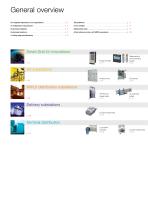
General overview Our adapted responses to your applications . . . . . . . . . . . . . . . . . . . . . . Customised reliability . . . . . . . . . . . . . . . . . . . . . . . . . . . . . . . . . . . . . . . . Customised solutions . . . . . . . . . . . . . . . . . . . . . . . . . . . . . . . . . . . . . . . . Article reference index, with ERDF equivalents . . . . . . . . . . . . . . . . . . . . p. 126 A cutting-edge test laboratory . . . . . . . . . . . . . . . . . . . . . . . . . . . . . . . . . Smart Grid LV innovations p. 15 Measurement and monitoring system p. 22 TIPI IP2X LV feeder pillars...
Open the catalog to page 2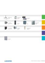
Flexible current sensors p. 26 Current shortcircuiting devices p. 56 "TUR" Compact LV feeder pillars p. 76 Load break switches p. 80 Fuses for public distribution p. 104 Static Transfer Systems p. 66 Public distribution catalogue
Open the catalog to page 3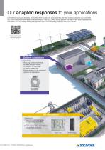
Our adapted responses to your applications Ever attentive to your requirements, SOCOMEC offers you services, products and customised solutions, whatever your constraints. As a French distribution switchboard manufacturer since 1965, SOCOMEC is a key player in the field of public electricity distribution. SOCOMEC's TIPI low voltage feeder pillars represent one of the best-selling products in the French market. Discover all our public distribution solutions on our website. Delivery substations Solutions for: • Reducing non-technical losses via highly accurate HV and LV metering, for new-build or...
Open the catalog to page 4
Energy storage Solutions for: • Optimising investments in the grid • Massive integration of renewable energies Services Pre-project phase: • Help with the design and realisation of customised solutions. • Qualification and certification testing (IEC 61439). On-site: • Commissioning • Equipment maintenance. • Supervision. Power Conversion System and Storage Smart MV/LV Distribution substation Solutions for: • Protection, distribution,measuring and monitoring of the LV electrical grid. • Securing the electrical supply and minimising maintenance. DIRIS Digiware Terminal distribution Solutions for:...
Open the catalog to page 5
An independent manufacturer The benefit of a specialist One of the leading independent power testing labs in Europe innovative! Since its foundation more than 90 years ago, SOCOMEC continues to design and manufacture its core products in Europe. Notably solutions for its primary mission: the availability, control and safety of low voltage electrical networks. on-site interventions per year of turnover invested in R&D Always at the cutting-edge of technology for innovative, high-quality products As an independent manufacturer, the Group is committed to constant innovation to improve the energy...
Open the catalog to page 6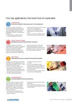
Four key applications: the know-how of a specialist Critical Power Ensuring the availability of high-quality power for critical applications. distortion and interruptions to the mains supply due to their power storage backup, • changeover of high availability sources to transfer supply to an operational backup source, • continuous monitoring of installation facilities to prevent failures and reduce operating losses. Thanks to the company’s wide range of continuously evolving products, solutions and services, SOCOMEC are experts in the three essential technologies that can ensure the high availability...
Open the catalog to page 7
Customised reliability for increased equipment durability As specialist manufacturers in the field of low voltage electrical facilities for over 90 years, Socomec offers a wide range of value-added services, a major factor in ensuring the reliability of your equipment throughout its design life. Take advantage of personalised support throughout your project and reach your energy objectives with confidence ! Public distribution catalogue Optimising equipment performance Maximising performance and anticipating any necessary changes will help you to better balance your budget. For this Socomec offers:...
Open the catalog to page 8
Customised solutions for implementations adapted to suit your needs To complement our standard offer, SOCOMEC has an organisation dedicated to the design and implementation of made-to-measure solutions. We are on-hand to offer support through the different phases of your project, from the analysis of specifications to the qualification of your solutions, up to implementation, commissioning and provision of on-site training. Please contact us for more information. Multi-field expertise We offer support throughout your project with our specialist teams of mechanical, electrical and IT engineers...
Open the catalog to page 9
A cutting-edge laboratory The backing of an expert Since 1965, the Pierre Siat test laboratory has used its expertise to guarantee the reliability and conformity of SOCOMEC products and solutions. Our customers are also welcome… Ongoing commitment Customized services Located at the Company’s headquarters in Benfeld (France), the Pierre Siat test laboratory is one of SOCOMEC’s main quality pillars: its contribution to the development, qualification and certification phases plays a decisive role in the process leading to the creation of a product or solution. To adapt to the increasingly demanding...
Open the catalog to page 10
Test platforms to guarantee UPS units and other high-quality power supply solutions Our test platforms use high performance equipment offering an extremely wide range of test options. All of SOCOMEC's products and solutions are submitted to the most rigorous tests of reliability and conformity by our in-house experts. A complete test system High-quality test capacities High level of activity • Routine tests performed on every product and on each solution. • Personalised demonstration and qualification tests. • Specific tests on request. • Tests on incoming goods and components • More than 300...
Open the catalog to page 11
www.socomec.com to be directly connected to our solutions Access multimedia content from your smartphone by scanning the codes available in our catalogues or documentations. a QR code application from your mobile phone (QR Code Sanner Pro, Mobiletag, ScanLife flashcode, etc.). 1 Find out about products, services and systems meeting the requirements of applications for which we have real expertise 2 Download documentations, pictures, logos and CAD files 4 Find answers to technical questions (FAQ) 5 Find out about our job offers 6 Get informed about our news: products, events and advice Download...
Open the catalog to page 12All SOCOMEC catalogs and technical brochures
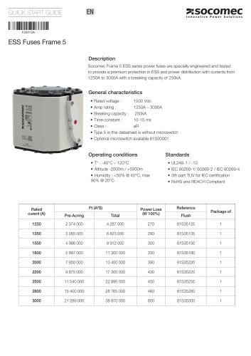 ESS Fuses Frame 5
2 Pages
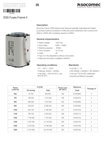 ESS Fuses Frame 4
2 Pages
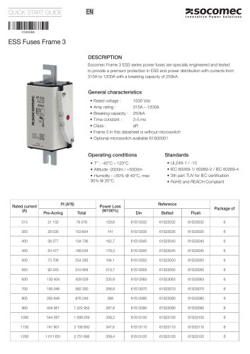 ESS Fuses Frame 3
2 Pages
 DIRIS Q800
4 Pages
 SURGYS® E10
2 Pages
 COMO CS
6 Pages
 GENERAL CATALOGUE 2021-2022
588 Pages


- Measuring device
- Dry transformer
- Surge protector
- Data logger
- Real-time software
- DIN rail lightning arrester
- Class II surge protector
- Measurement software
- Humidity and temperature probe
- Wireless datalogger
- Digital gauge
- Datalogger without display
- Low-voltage lightning arrester
- Lithium battery
- DIN rail electric energy meter
- Industrial transformer