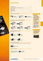
Overview: The 2015 SOCOMEC catalogue provides a comprehensive guide to changeover switching solutions, focusing on transfer switching equipment ranging from 40 to 6300 A. It includes manual, modular, and motorised transfer switches, as well as automatic control technologies.
Key Sections:
- Manual Transfer Switches: Details on SIRCOVER switches, including bypass options for 125 to 3200 A.
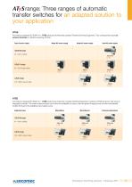
- Motorised Transfer Switches: Information on the ATyS range, including various models like ATyS S, ATyS d, and ATyS g, with capabilities from 40 to 6300 A.
- Automatic Control Technologies: Describes the universal N/E controller and UL product range, supporting automatic control of circuit breakers, contactors, and switches.
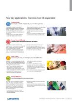
- SOCOMEC Group Overview: Highlights SOCOMEC's commitment to innovation, energy performance, and adherence to international standards, with a focus on critical power, power control and safety, solar power, and energy efficiency.
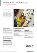
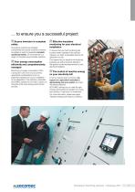
- Services & Technical Assistance: SOCOMEC offers a range of services including assessment, commissioning, maintenance, and training to ensure optimal use of their products.
- Testing and Quality Assurance: The Pierre Siat test laboratory plays a crucial role in ensuring the reliability and conformity of SOCOMEC products.
Critical Information: SOCOMEC emphasizes the importance of ensuring power supply continuity and operational safety through innovative source transfer solutions. The catalogue also highlights the company's expertise in energy efficiency and the management of reactive energy.
Accreditations and Partnerships: The document outlines the Pierre Siat laboratory's accreditations by major certification bodies such as ASEFA, LOVAG, COFRAC, UL, CSA, and KEMA. It collaborates with international certification organizations to ensure compliance with quality and safety requirements specific to each country.
Laboratory Facilities: The laboratory is equipped with a 100 MVA short-circuit platform, three 10 kA overload platforms, and various test instruments over a 1500 m2 area. It is the second-largest power laboratory in France, specializing in electricity, mechanics, pneumatics, and computing.
Testing Capabilities: The Pierre Siat laboratory conducts a wide range of tests on SOCOMEC products, including functional, dielectric, mechanical, environmental, AC/DC endurance, temperature rise, electromagnetic compatibility, metrology, and safety tests. These tests ensure the long-term reliability of the equipment.
Customized Services: The laboratory offers its testing facilities and expertise to partners for product qualification and certification. Certificates of conformity and performance declarations are available upon request.
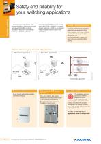
Product Range and Applications: SOCOMEC provides a range of transfer switches from manual to automatic, covering applications from 25 A to 3200 A. The products are designed for mains/genset and mains/mains applications, ensuring safety and reliability in electrical distribution.
Special Products and Services: SOCOMEC develops special products like make-before-break contacts and mixed pole motorized transfer switches. The Services & Technical Assistance department offers installation assessment, equipment commissioning, and personnel training.
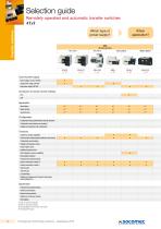
Transfer Switches Specifications: The document details the specifications of various SOCOMEC transfer switches, including RTSE and ATSE products, which comply with IEC 60947-6-1 standards. It provides a selection guide for different power supply types and applications.
SIRCOVER Manual Transfer Switches: SIRCOVER switches are available in three versions for open transition, overlapping contact switching, and bypass applications. They offer stable positions, easy connections, and improved on-load switching, conforming to IEC 60947-3 and IEC 60947-6-1 standards.
Specifications: The SIRCOVER switches are categorized by their rating (A), frame size, handle color, and type. They are available in different configurations such as I-0-II and I-I+II-II, with protection degrees specified according to IEC 60529 standards (IP55 and IP65).
Handle Types and Colors: Handles are available in blue, red, and black, with types including J2, C1, C2, S2, S3, S4, and S5. The document specifies the reference numbers for each configuration.
External Operation Handles: These handles are door interlocked, padlockable, and require an extension shaft for operation. They are designed for front operation and include escutcheons.
Bridging Bars: Used for creating common connections between switches, bridging bars are essential for SIRCOVER Bypass configurations. They are specified by rating, frame size, number of poles, and section dimensions.
Shaft Guides and Extensions: Shaft guides facilitate the alignment of extension shafts with external handles, accommodating misalignments up to 15 mm. Standard shaft lengths are 200 mm, 320 mm, and 450 mm, with custom lengths available upon request.
Auxiliary Contacts: These contacts provide pre-breaking and signaling for positions I and II, with options for 1 or 2 NO/NC contacts. They are connected via fast-on terminals and are rated for 30,000 operations.
Copper Bar Connection Kits: These kits enable connections between power terminals for ratings from 2000 to 3200 A. They include various parts such as connection pieces, bolt sets, T pieces, and brackets, with specific ordering instructions for different configurations.
Terminal Shrouds and Screens: Designed for protection against direct contact, these accessories allow for thermographic inspection without removal. They are specified by rating, frame size, number of poles, and position.
Inter-phase Barriers: These provide safety isolation between terminals, crucial for use at 690 VAC or in polluted environments.
Key Handle Interlocking System: This system allows for padlocking and locking using a RONIS EL11AP lock, with configurations for different positions and operations.
Specifications: The manual transfer switches are categorized by their current ratings and frame sizes, with options ranging from 125 A to 3200 A. The document specifies the rated insulation voltage (Ui) and impulse withstand voltage (Uimp) for different frame sizes, ensuring compliance with IEC 60947-3 and IEC 60947-6-1 standards.
Locking Mechanisms: Various locking options are available, including the use of padlocks, RONIS EL11AP locks, and K-type CASTELL locks. The document details the configurations for locking in different positions (I, 0, II) and the use of undervoltage coils for enhanced security.
Operational Characteristics: The switches are designed for both frequent (A) and infrequent (B) operations, with specific ratings for operational currents (Ie) across different voltage levels (415 VAC, 500 VAC, 690 VAC, and 220/440 VDC). The document also outlines the operational power in AC-23 and reactive power ratings.
Dimensions and Installation: Detailed dimensions for each switch rating are provided, including height, width, depth, and weight. The document specifies the materials used, protection degree (IP54), and installation guidelines, such as wall mounting and door locking mechanisms.
Accessories: A range of accessories is available, including customized protection screens, connection accessories, and auxiliary contacts. The document emphasizes the importance of using appropriate accessories to ensure optimal performance and safety.
Safety and Compliance: The switches are designed to withstand mechanical risks and dust hazards, with specific coatings and materials used to enhance durability. Compliance with international standards ensures reliability and safety in various operational environments.
Impulse Withstand Voltage and Rated Operational Currents: The document outlines the impulse withstand voltage (Uimp) for various devices, ranging from 8 kV to 12 kV. It also details the rated operational currents (Ie) for different voltage categories (415 VAC, 690 VAC, 220 VDC, 440 VDC) and utilization categories (A/B), with currents ranging from 125 A to 1600 A.
Operational Power and Reactive Power: Operational power in AC-23 is specified for 400 VAC and 690 VAC without pre-break, with values ranging from 63 kW to 710 kW. Reactive power at 400 VAC is also provided, ranging from 55 kvar to 575 kvar.
Short-Circuit Withstand and Connection Specifications: The document provides details on fuse-protected short-circuit withstand capacities, prospective short-circuit ratings, and associated fuse ratings. It also specifies the minimum and maximum copper cable and busbar cross-sections, as well as tightening torque requirements.
Mechanical Characteristics: Durability is measured in operating cycles, ranging from 3,000 to 10,000 cycles. The weight of 3-pole and 4-pole switches is provided, with weights ranging from 8.3 kg to 67.3 kg.
Dimensions and Installation: Dimensions for manual transfer switches (SIRCOVER ATS Bypass) are detailed for ratings from 125 A to 1600 A. The document includes specifications for direct and external front operation, with overall dimensions and connection details.
Automatic Transfer Switch Equipment (ATyS): The document describes the ATyS M range, which includes remotely operated and automatic transfer switches. Key features include electrical and mechanical interlocking, positive break indication, padlocking options, and high performance with on-load making and isolation. The ATyS range is designed for easy installation and rapid commissioning, with intuitive use and simplified configuration options.
Overview: The document is a catalogue for the ATyS range of transfer switches, offering automatic and remotely operated solutions for electrical systems ranging from 40 to 160 A. These switches are designed for secure and reliable operation in low voltage power supply systems.
Specifications: The ATyS range includes models such as ATyS M, ATyS d M, ATyS t M, and ATyS g M, each catering to different applications like mains/mains and mains/genset configurations. They comply with standards IEC 60947-6-1 and IEC 60947-3, ensuring high performance and safety.
Key Features:- Secure Operation: Electrical and mechanical interlocks, positive break indication, and padlocking options enhance safety.
- High Performance: On-load making and isolation, immunity to voltage fluctuations, and low blackout times (<90ms) are highlighted.
- Compact Design: All-in-one solutions minimize installation errors and simplify the ordering process.
- Ease of Use: Manual emergency control and simple mode selection (Auto/Manual) are provided.
- Rapid Commissioning: Minimal configuration time is required, with some models needing no configuration at all.
Installation and Configuration: The switches are designed for easy installation with features like DIN rail mounting, cage terminals, and bridging bars. Configuration is user-friendly, with options for impulse and contactor logic control.
Applications: The ATyS switches are suitable for use in building management systems, data centers, healthcare facilities, and high-rise buildings, providing solutions for secure operation, high performance, and fast transfer times.
Product Variants: The document lists various models with specific ratings and configurations, including single-phase and three-phase options, along with accessories like auxiliary contact blocks and sealable covers.
Overview: The document provides detailed information on the ATyS M range of Automatic Transfer Switching Equipment (ATSE) designed for low voltage power supply systems. These products are self-powered from incoming supplies and are suitable for applications where brief interruptions are acceptable.
Specifications: The ATyS M range includes models ATyS t M, ATyS g M, and ATyS p M, supporting ratings from 40 to 160 A. They operate on 230 VAC (176-288 VAC) and 50/60 Hz (45/65 Hz) networks. The equipment conforms to standards IEC 60947-6-1, IEC 60947-3, and GB 14048.11.
Key Features:- ATyS t M and ATyS g M: These models include an integrated ATS controller for mains/mains and mains/genset applications, respectively. They offer fast commissioning with simple configuration using potentiometers and DIP switches.
- ATyS p M: This model offers flexible programming, a trip function, Modbus communication, and a remote control interface. It is designed for both single-phase and three-phase applications.
Applications: The ATyS M range is suitable for high-rise buildings, data centers, healthcare facilities, banking, insurance, and transportation sectors.
Accessories: The document lists various accessories such as bridging bars, terminal shrouds, voltage sensing taps, auxiliary contact blocks, sealable covers, and polycarbonate enclosures to enhance the functionality and security of the ATSE.
Configuration and Software: The Easyconfig software is available for configuring the ATyS p M model, allowing users to set application types, voltage/frequency thresholds, timers, and inputs/outputs.
Conclusion: The ATyS M range provides a comprehensive solution for automatic transfer switching needs, offering flexibility, ease of use, and compliance with international standards.
Overview: The document provides detailed specifications and descriptions of the ATyS M range of transfer switches, including models ATyS d M, ATyS t M, ATyS g M, and ATyS p M, which are designed for use in electrical systems ranging from 40 to 160 A. It covers various components, accessories, and configurations available for these products.
Specifications: The ATyS M range is designed for three-phase and single-phase applications. The products are rated for 40 to 160 A and have a rated insulation voltage of 800 V for the power circuit and 300 V for the operation circuit. The impulse withstand voltage is rated at 6 kV.
Components and Accessories: - Terminal Shrouds: Feature perforations for remote thermographic inspection and can be fitted with tamper-proof seals.
- Voltage Sensing and Power Supply Tap: Allows connection of voltage sensing or power cables without reducing terminal capacity.
- Auxiliary Contacts: Used for position indication, with a maximum of two blocks per product, each integrating three NO/NC contacts.
- Sealable Cover: Prevents access to configuration panels, with seals and screws included.
- Polycarbonate Enclosure: Facilitates the installation of a three-phase ATyS M, providing a compact transfer switch solution.
- Extension Box: Provides additional space for connecting larger cables.
- Residential Enclosure: Offers a compact IP41 solution for single-phase ATyS M integration.
- Double Power Supply (DPS): Allows the ATyS d M to be supplied by two networks, ensuring control over power transfer.
- Auto-transformer: Provides the necessary 230 VAC for ATyS M in 400 VAC applications without a distributed neutral.
- Remote Interfaces: D10 and D20 interfaces display source availability and position indication, with the D20 offering additional measurement and control capabilities.
- Power Connection Terminals: Convert cage terminals to bolt-on type, supporting larger cable connections.
Enclosed Transfer Switch Solutions: These solutions are designed to mitigate mechanical risks and dust hazards, featuring integrated bridging bars and protection degrees of IP3x or IP54. They are constructed from steel with an epoxy polyester powder coating and include hinged metal doors with locks.
General Characteristics: The document lists various models with their respective ratings, number of poles, and references for both IP3X and IP54 protection levels. It also provides dimensions and weight details for the enclosures.
Standards Compliance: The ATyS M range complies with IEC 60947-3 and IEC 60947-6-1 standards, ensuring reliability and safety in electrical installations.
Specifications: The document outlines the specifications for the ATyS M range of transfer switches, which include models ATyS d M, ATyS t M, ATyS g M, and ATyS p M, with operational currents ranging from 40 to 160 A. The rated impulse withstand voltage for the operation circuit is 4 kV for ATyS d M and 2.5 kV for ATyS t M, g M, and p M. The rated operational currents are specified according to IEC 60947-6-1 and IEC 60947-3 standards, with various utilization categories for different voltage levels.
Procedures and Standards: The document adheres to IEC 60947-6-1 and IEC 60947-3 standards, ensuring compliance for transfer switches. It also mentions the coordination with circuit breakers for short-circuit protection, specifying a tripping time of less than 0.3 seconds.
Mechanical Characteristics: The switches have a durability of 10,000 operating cycles and are available in both single-phase and three-phase versions, with weights specified for each. The document also details the connection requirements, including cable cross-sections and tightening torque.
Power Supply and Control: The power supply for the ATyS d M, t M, and g M models ranges from 176 to 288 VAC, while the ATyS p M model ranges from 160 to 305 VAC. The control supply power demand is 6 VA, with maximum currents specified for different models.
Switching Solutions: The ATyS S range is highlighted as a robust solution for transfer switches, offering features like stable positions, positive break indication, and mechanical position interlocking. It supports dual power supply and is designed for easy integration and maintenance.
Advantages: The ATyS S range offers extensive power supply options, safety and reliability through stable position technology, and easy integration due to its compact design. It also provides cost-saving benefits through low power consumption and easy installation.
Applications: The ATyS S and ATyS d S models are suitable for applications such as gensets, heating systems, climate control, ventilation systems, and telecommunications, offering a range of power supply options and simplified maintenance.
Overview: The document provides detailed information on the ATyS S and ATyS d S remotely operated transfer switching equipment, designed for applications ranging from 40 to 125 A. These switches are suitable for various systems including gensets, heating, climate control, ventilation, and telecommunications.
Specifications: The ATyS S products are 4-pole transfer switches that allow the on-load transfer of two three-phase supplies. They are compliant with IEC 60947-6-1, IEC 60947-3, and GB 14048-11 standards. The switches are available in different power supply versions: 12 VDC, 24/48 VDC, 230 VAC, and dual 230 VAC.
Key Features:- Extensive Power Supply Range: Offers a broad range of power supply options.
- Safety and Reliability: Utilizes stable position technology to ensure constant contact pressure and prevent faults.
- Easy Integration: Compact design allows for easy installation in most enclosures.
- Simplified Maintenance: Maintenance can be performed under load, with easy replacement of control and motorization sections.
- Dual Power Supply (ATyS d S): Incorporates supply redundancy without additional wiring.
Accessories and Spares: The document lists various accessories such as DIN rails, bridging bars, terminal shrouds, and voltage taps. It also details spare parts like motorization units, switching units, and manual emergency operation handles.
Technical Characteristics:- Thermal Current: Ranges from 40 A to 125 A.
- Rated Insulation Voltage: 800 V for power circuits and 300 V for operation circuits.
- Short-Circuit Capacity: Detailed specifications for fuse and circuit breaker protection.
- Mechanical Characteristics: Durability of 25,000 operating cycles and a weight of 3 kg for both ATyS S and ATyS d S models.
Enclosed Transfer Switch Solutions: The document describes enclosed solutions with features like IP3X protection (IP54 optional), wall mounting options, and manual emergency operation handles. It also provides dimensions and connection details for different ratings.
Conclusion: The ATyS S and ATyS d S switches offer a reliable and versatile solution for transfer switching needs, with a focus on safety, ease of integration, and maintenance.
Specifications: The document outlines the specifications for the ATyS range of remotely operated transfer switching equipment, covering rated operational currents, voltage utilization categories, and short-circuit withstand capabilities. The equipment is designed for use in low voltage power systems and complies with IEC 60947-3 and IEC 60947-6-1 standards.
Rated Operational Currents: The equipment supports rated operational currents ranging from 40A to 125A, with various utilization categories (AC-20, AC-21, AC-22, AC-23) at 415 VAC. The short-circuit withstand capacity varies depending on the protection method, with fuse-protected and circuit breaker-protected options available.
Power Supply and Control: The equipment operates on multiple power supply options, including 12 VDC, 24/48 VDC, and 230 VAC, with specific inrush and nominal power demands. Control supply power demand is consistent across all models.
Mechanical Characteristics: The equipment is designed for durability, with a lifespan of 25,000 operating cycles and a consistent weight across models. Connection specifications include a maximum Cu cable cross-section of 50 mm² and a tightening torque range of 1.2 to 3 Nm.
Switching Time: Standard switching times are specified for different operations, ensuring minimal electrical blackout duration.
Product Range and Features: The ATyS range includes various models such as ATyS r, ATyS d, ATyS t, ATyS g, and ATyS p, each offering unique features like dual power supply, automatic controllers, and energy management functions. The equipment is designed for safe operation, robust integration, intuitive use, rapid commissioning, and easy maintenance.
Applications and Advantages: The ATyS r and ATyS d models are suitable for applications with external ATS/AMF controllers and building management systems. They feature a watchdog relay for product availability monitoring, integrated auxiliary contacts, and an extended power supply range. The ATyS d model includes an integrated dual power supply for redundancy.
Compliance and Standards: The equipment complies with IEC 60947-6-1 and IEC 60947-3 standards, ensuring reliability and safety in operation.
Overview: The document is a technical catalogue for ATyS transfer switching equipment, detailing various models and their specifications, applications, and advantages. The equipment is designed for low voltage power systems and includes both remotely operated and automatic transfer switches.
Specifications: The ATyS r and ATyS d models are remotely operated transfer switches available in three-phase configurations with 3 or 4 poles, supporting current ratings from 125 to 3200 A. They feature a positive break indication and are compatible with external automatic controllers. The ATyS t and ATyS g models are automatic transfer switches designed for mains/mains and mains/genset applications, respectively. They offer rapid commissioning and are equipped with integrated controllers for specific applications.
Key Features:- Watchdog Relay: Monitors product availability in real-time.
- Integrated Auxiliary Contacts: Provide position information for monitoring purposes.
- Extended Power Supply Range: Supports 208 to 277 VAC ± 20%.
- Dual Power Supply (ATyS d): Offers supply redundancy without additional wiring.
- Rapid Commissioning (ATyS t and g): Configuration through potentiometers and DIP switches.
- Event Recording (ATyS p): Timestamped event recording for effective monitoring.
- Optional Communication Modules (ATyS p): Supports Modbus and Ethernet communication.
Conformity to Standards: All models conform to IEC 60947-6-1 and IEC 60947-3 standards.
Applications: The equipment is suitable for applications requiring power management, communication, and energy monitoring. It is designed for use in systems where brief interruptions during power source transfer are acceptable.
Technical Information: The document includes detailed technical specifications, references for different models, and information on accessories, characteristics, terminals, connections, and dimensions.
Overview: The document provides detailed information about the ATyS p Automatic Transfer Switching Equipment, which ranges from 125 to 3200 A. It highlights the functionalities, specifications, and optional modules available for the equipment, focusing on power management and communication capabilities.
Webserver Functionality: The ATyS p includes a webserver function embedded in the Ethernet communication module. This allows users to access HTML pages via an internet browser by entering the IP address. The webserver provides functionalities such as displaying source status, switch position, main measurements, extracting logged events, and displaying product configuration.
Specifications: The ATyS p is a three-phase automatic transfer switch available in 3 or 4 poles with positive break indication. It is designed for low voltage power supply systems where brief interruptions are acceptable. The equipment supports Modbus and Ethernet protocols for communication.
Configuration and Monitoring: The Easyconfig software simplifies the configuration process, allowing users to set parameters like application type, voltage/frequency thresholds, timers, and inputs/outputs. The equipment also supports event recording with timestamped logs accessible via the communication system.
Optional Modules and Accessories: The document lists various optional modules such as RS485 Modbus communication, Ethernet communication, analogue outputs, and pulse outputs. It also details accessories like bridging bars, terminal screens, and shrouds for enhanced protection and connectivity.
Standards and Compliance: The ATyS p complies with IEC 60947-6-1 and IEC 60947-3 standards, ensuring reliability and safety in its operations.
Applications: The equipment is suitable for applications requiring power management and communication, offering features like periodic genset startup for maintenance purposes.
Overview: This document provides technical specifications and accessory details for the ATyS range of transfer switches, including models ATyS r, d, t, g, and p, with current ratings from 125 to 3200 A. It includes information on remote interfaces, connection cables, and various optional modules and accessories.
Specifications:- RJ45 Cable: 8-wire straight-through, non-isolated cable, 3m length, used for connecting remote interfaces to ATyS transfer switches.
- Remote Interfaces: D10 and D20 models for displaying source availability and position indication. D20 also allows control and configuration. Both have a protection degree of IP21.
- Double Power Supply (DPS): Allows ATyS r to be supplied by two 230 VAC networks, with internal fuse protection and modular design.
Accessories:- Sealable Cover: Prevents unauthorized access to configuration settings on ATyS t and g models.
- Auto/Manual Key Selector: Replaces standard selector knob for added security.
- Plug-in Optional Modules: Available for ATyS p, including RS485 MODBUS communication, Ethernet communication, analogue outputs, and pulse outputs.
Spare Parts: Electronic, motorisation, and switching modules can be replaced for ATyS models, with specific references provided for each.
Enclosed Transfer Switch Solution: Features include IP54 protection, XC steel construction, and options for wall or floor mounting. Available for ATyS d and p models with various ratings and dimensions.
Standards and Ratings: The document outlines operational currents, insulation voltages, and short-circuit withstand capabilities according to IEC standards for different ATyS models and configurations.
Overview: The document is a technical catalogue detailing the specifications, functions, and advantages of the ATyS d H remotely operated transfer switching equipment, designed for high power applications ranging from 4000 to 6300 A. It also covers the ATyS C20/C30/C40 control relays used for automatic control of transfer switches.
Specifications: - ATyS d H: Designed for low voltage high power applications, it supports 3 and 4 pole configurations. It offers high performance switching with a short circuit current rating of 143kA Icm and 65kA for 0.1sec Icw. The device is compliant with IEC 60947-6-1 and GB 14048-11 standards.
- ATyS C20/C30/C40: These are modular control relays ensuring automatic control of transfer switches and are compatible with various technologies including contactors and circuit breakers. They conform to IEC 61010-1, IEC 61000-4-x, and IEC 60068-2-x standards.
Functions: - ATyS d H: It performs open transition transfers on-load, ensuring minimal power supply interruption. It includes two mechanically interlocked switches for safe on-load transfer, providing a neutral position for maintenance.
- ATyS C20/C30/C40: These relays provide auxiliary power supply options, modular design for DIN-rail mounting, and extended compatibility with various switching technologies. They offer programmable inputs and outputs for various control functions.
Advantages: - ATyS d H: The device is designed for easy installation with rear power connections and does not require external bridging bars. It supports high performance switching and safe on-load transfer.
- ATyS C20/C30/C40: These relays offer power and control separation, compatibility with genset applications, and modular design for ease of use.
Applications: The equipment is suitable for data centers, telecommunications, and industrial applications, providing high performance and reliable switching solutions.
Key Data: - Thermal current ratings: 4000 A, 5000 A, 6300 A.
- Rated operating voltage: 660 V.
- Switching time: I to 0 ≤ 150 ms, 0 to I and 0 to II ≤ 90 ms.
- Durability: 3000 operating cycles.
Overview: The document provides detailed technical specifications and functionalities of the ATyS C20, C30, and C40 control relays, as well as the SIRCOVER UL 1008 manual transfer switches. These devices are used for automatic and manual transfer of electrical loads between different power sources, ensuring continuity and safety in power supply systems.
Specifications:- ATyS C20/C30/C40: These are modular control relays designed for automatic control of transfer switches and other motorized switches. They support both AC and DC power supplies, with a measurement range of 110-400 VAC and frequency of 50/60 Hz. The accuracy is ±1%.
- SIRCOVER UL 1008: These are heavy-duty manual transfer switches, capable of handling 100 to 1200 A. They are designed for safe transfer and disconnection of power sources, with stable positions unaffected by voltage drops or vibrations.
Functions and Features:- ATyS C20/C30/C40: These devices provide control and position information feedback, genset start/stop control, and have programmable inputs and outputs for various functions such as source availability and circuit breaker control. The C30 version includes a display/interface connection.
- SIRCOVER UL 1008: These switches ensure maintenance-free operation with robust design, integrated switch disconnection, and a stable OFF position for safe maintenance. They provide quick and safe manual operation with positive break indication.
Applications:- ATyS UL 1008: Suitable for mains/genset and genset/genset applications, providing safe transfer for optional standby power systems. They are compatible with various ATS, AMF, and genset controllers.
- SIRCOVER UL 1008: Used for safe transfer and disconnection in low voltage installations, suitable for changing motor phases or equipment grounding.
Standards and Compliance:- ATyS devices conform to IEC 61010-1, IEC 61000-4-x, and IEC 60068-2-x standards.
- SIRCOVER UL 1008 complies with UL 1008, UL 98, and CSA 22.2#4 standards.
Advantages:- Modular design for easy installation and compatibility with various technologies.
- Robust and reliable design ensuring safety and power control.
- Stable positions and quick operation for manual switches.
Overview: The document provides detailed information about the SIRCOVER UL 1008 Manual Transfer Switching Equipment, which is designed for safe transfer and disconnection of low voltage circuits on load. It is suitable for demanding applications and offers reliable performance with features like stable positions, compact design, and on-load switching capabilities.
Specifications:- Rated for 100 to 1200 A.
- Conforms to UL 1008, UL 98, and CSA 22.2#4 standards.
- Suitable for manufacturing, power distribution, and domestic applications.
- Available in versions for resistive and total systems applications.
Key Features:- Three stable positions unaffected by voltage drops or vibrations.
- Compact design with back-to-back switching technology.
- Double breaking per pole with sliding bar contacts system.
- Quick opening and rapid closure for simultaneous disconnecting or making of all power contacts.
Applications:- Safe transfer and disconnection within LV installations.
- Changing motor phase for rotation control or equipment grounding.
- Normal power supply to genset transfer, operable under on-load or over-load conditions.
Accessories:- Various handle types and lengths for external and direct handles.
- Bridging bars for creating common points between positions.
- Auxiliary contacts for pre-break and signalization of positions.
- Terminal protection screens for safety against direct contact.
- Terminal lugs for connecting bare copper cables.
Performance Characteristics:- Operational voltage ranges from 240 to 600 VAC.
- Short circuit ratings vary with circuit breaker types and configurations.
- Mechanical endurance ranges from 3050 to 6050 operating cycles depending on the model.
- Connection terminals support a range of wire sizes and configurations.
Certifications:- UL 1008 and UL 98/CSA 22.2#4 certifications ensure compliance with safety and performance standards.
Conclusion: The SIRCOVER UL 1008 series offers a robust solution for manual transfer switching needs, with a focus on safety, reliability, and compliance with industry standards. It is versatile for various applications and comes with a range of accessories to enhance its functionality.
Overview: The document provides detailed information about the ATyS UL 1008 Motorized Transfer Switching Equipment, which is designed for commercial, light industrial, and residential applications. It covers specifications, compatibility, typical applications, and accessories.
Specifications: The ATyS UL 1008 range supports motorized transfer switching from 100 to 400 A. It is compatible with virtually any ATS controls that provide volt-free contacts, allowing integration with various automatic transfer switch applications. The equipment is compliant with UL 1008 standards and is part of a globally recognized product family.
Compatibility and Applications: The ATyS is compatible with most ATS controls available on the market, making it suitable for mains/mains, mains/genset, and genset/genset applications. It is trusted by major manufacturers in the genset industry for its reliability and ease of use.
Standards and Conformity: The equipment conforms to UL 1008 standards, ensuring safety and reliability in transfer switching operations. It is part of a product range that complies with IEC and GB standards.
Accessories and Options: The document lists various accessories such as bridging bars, terminal screens, auxiliary contacts, and lug kits. It also provides details on spare parts like motorization modules and terminal lugs.
Technical Characteristics: The ATyS UL 1008 features a general use rating of 100 to 400 A, with operational voltages of 240/600 VAC. It has a short circuit rating with any circuit breaker and specific circuit breakers, and it supports both single-phase and three-phase operations. The equipment has a mechanical endurance of up to 6050 operating cycles.
Dimensions and Installation: Detailed dimensions for the ATyS UL 1008 are provided, along with recommended enclosure dimensions for installation. The document includes diagrams for typical wiring configurations and control outputs.
Overview: This document is a technical guide on enclosed transfer switch solutions, specifically focusing on Automatic Transfer Switch Equipment (ATSE) ranging from 40 to 3200 A. It provides detailed specifications, procedures, and standards compliance for ensuring continuous power supply to critical loads.
Specifications: The ATSE operates at 230/400 VAC with a frequency of 50/60 Hz and is self-powered from incoming sources. It supports a normal/emergency logic control sequence, voltage and frequency checking, phase rotation control, and includes a configurable output relay for generator start/stop commands. The equipment is protected to IP41 standards, with options for higher protection levels upon request.
Procedures: The document outlines the automatic transfer of two supply sources to maintain power continuity during maintenance and testing. It describes the use of a remote interface for easy configuration and data visualization. The ATSE includes manual emergency operation and auxiliary contacts for enhanced functionality.
Standards and Compliance: The ATSE complies with IEC 61439-2, IEC 60947-6-1, IEC 60947-3, and BS 60947-6-1 standards, ensuring reliability and safety in various applications.
Applications: The solutions are suitable for data centers, power production, healthcare buildings, high-rise buildings, banking and insurance, and transportation sectors.
Recommendations: The document recommends using extension cabinets for easier wiring and future adaptations, and provides options for overvoltage protection, multifunction meters, and tinned busbars for severe environmental conditions.
Accessories: Optional accessories include a mimic panel for system status overview, engine exerciser for genset management, and customer-fit modules for additional inputs/outputs.
Key Data: The document includes tables with ratings, dimensions, and references for single and double line ATS Bypass configurations, as well as recommended connection cross-sections for various current ratings.
Introduction: The document discusses the concept of transfer switching, which involves switching operations between two power circuits. This is crucial for applications requiring a backup power supply, such as hospitals and other critical installations.
Applications:- Normal/Emergency Applications: These involve switching to an alternate power supply when the main supply fails, ensuring continuity for critical systems like lighting and fire alarms.
- Genset/Genset Applications: Utilized when two generators supply the load.
- Switching Between Loads: Provides redundancy and balanced operating time.
- Earthing: Safely isolates a load from the supply for maintenance.
- Phase and Rotation Inversion: Alters motor rotation direction with a delay to prevent damage.
- Bypass: Allows maintenance by isolating equipment while maintaining supply via a parallel circuit.
Transfer Switching Equipment (TSE) in LV Installations: These are essential for safety installations, ensuring continuous power supply to critical systems.
Types of Transfer Switching:- Break Before Make (Open Transition): Ensures no overlap between main and alternate sources, with a minimum off-time of 50 ms as per IEC 60947-6-1.
- Closed Transition (Synchronous Transfer): Allows temporary parallel operation of sources for scheduled transfers, requiring synchronization of phase angles and frequencies.
- Asynchronous Transfer: Suitable for large motor loads, allowing rapid transfer without stopping the motor.
Types of Sources and Load Criticality:- Priority Source: Typically a power grid with redundancy options.
- Alternative Source: Includes gensets, turbines, and UPS systems.
- Load Classification: Based on criticality and sensitivity, ranging from critical equipment requiring UPS to non-essential equipment.
Choosing the Right Changeover Switch: Socomec changeover switches ensure efficient energy distribution and continuity. Selection criteria include control type and installation restrictions, with solutions based on open transition switching to prevent source overlap.
Conclusion: The document provides comprehensive guidelines on transfer switching solutions, emphasizing safety, efficiency, and compliance with international standards.
Overview: The document provides a comprehensive guide on low voltage electrical installations, focusing on the use of SOCOMEC transfer switches to ensure continuity of power supply. It categorizes equipment based on criticality and outlines the specifications and advantages of different switching solutions.
Key Sections:
1. Equipment Categorization: Equipment is divided into critical, essential, and non-essential categories. Critical equipment requires continuous power, essential equipment needs quick power restoration, and non-essential equipment is powered only after normal supply resumes.
2. Standards and Safety: According to NFC 15-100, safety power supplies are crucial for maintaining operational conditions of devices critical for personal safety. The document references NFC 15 211 for medical premises, highlighting the importance of power supply in critical environments.
3. Transfer Modes and Emergency Sources: The choice of transfer mode and emergency sources depends on the load's criticality. The document provides examples of load criticality and outlines different shutdown categories based on transfer time requirements.
4. SOCOMEC Transfer Switches: SOCOMEC offers solutions for efficient power distribution continuity. The document details the selection criteria for changeover switches, including control type and installation restrictions. It emphasizes the benefits of open transition switching and interlocking to prevent overlap between power sources.
5. Electrical Diagrams and Solutions: Various diagrams illustrate technical solutions using SOCOMEC transfer switches. These solutions cater to different installation architectures, such as single or multiple busbars, and include truth tables to explain operation scenarios.
6. Advantages of SOCOMEC Solutions: SOCOMEC solutions offer compact design, plug-and-play implementation, and built-in mechanical and electrical interlocking. They reduce the number of required products and enhance system reliability.
7. Product Specifications: The document lists specific SOCOMEC products, such as ATyS models and SIRCO MOT AT, detailing their applications in different power supply configurations.
Implementation:- Compact design with plug and play capability.
- Built-in mechanical and electrical interlocking.
Operation:- Reduced number of emergency handles (2 instead of 3).
- Secured padlocking system for enhanced safety.
Advantages of the Socomec Solution:- Supports various configurations such as Genset/Genset and Mains/Mains - Mains/Genset.
- Compatible with ATyS models including ATyS d M, ATyS r, ATyS S + C40, and others.
Low Voltage Installation:- Transfer between 3 sources and 2 busbars with different architectural types.
- Truth tables provided for typical and Socomec solutions.
Automatic Transfer:- ATS Controller can be external or integrated, monitoring voltages and frequencies.
- Ensures backup source availability and consistent phase rotation.
Test Cycles:- Includes Test On Load and Test Off Load for periodic maintenance.
- Engine Exerciser function for scheduled tests.
Specific Applications:- Automatic transfer inhibition for remote intervention.
- Periodic reallocation of priority source between transformers.
Priority Source Selection and Transfer Control: The document discusses the management of power sources for transformers, focusing on selecting a priority source based on load power consumption and source capacity. Priority can be adjusted locally or remotely, maintaining specific time and cycle sequences.
Controlled Transfer: Transfers back to the priority source can be automatic or manual, allowing controlled load switching. The system remains operational to initiate transfers if the emergency source fails.
External Control: The system allows remote or manual activation of switch positions, overriding automatic operations. A function to return to position 0 without power supply is available to protect loads from unstable sources.
Load Shedding: In emergency mode, partial load feedback is possible, allowing the backup source to have lower capacity than the normal source. Load shedding can be controlled via a specific contact before transferring to the emergency source.
IEC 60947-6-1 Standard: This standard applies to transfer switching equipment (TSE) for systems up to 1,000 Vac or 1,500 Vdc, covering manually, remotely, and automatically operated equipment. TSE is classified by control method and short-circuit capability, with specific classes (PC, CB, CC) defining their capabilities.
Utilisation Categories: TSE must comply with rated making and breaking capacities and operational performance requirements. Categories are designated with suffixes A or B based on operational needs.
Product Markings: Products must reference the IEC 60947-6-1 standard, ensuring they are designed and tested for source changeover applications.



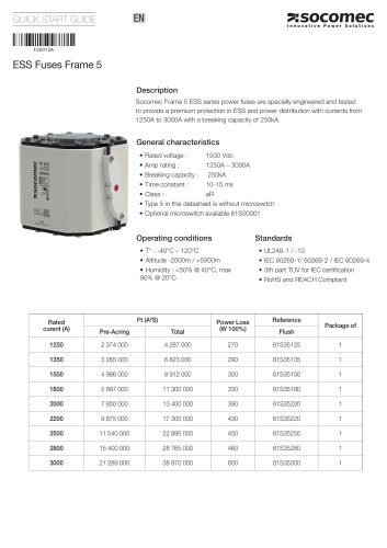 ESS Fuses Frame 5
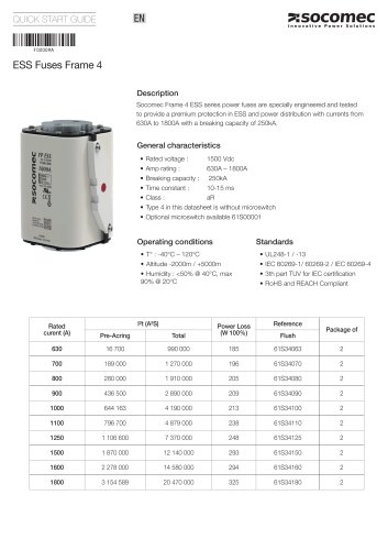 ESS Fuses Frame 4
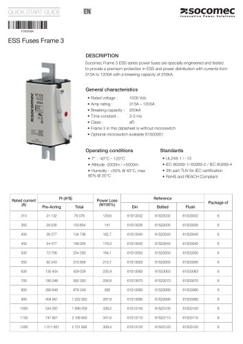 ESS Fuses Frame 3
 DIRIS Q800
 SURGYS® E10
 COMO CS
 GENERAL CATALOGUE 2021-2022
 Public distribution catalogue


