- Catalogs
- Smiths Interconnect
- VME64X Catalogue
- Company
- Products
- Catalogs
- News & Trends
- Exhibitions
VME64X Catalogue
1 /12Pages

VME64X Catalogue
1 /12Pages
Catalog excerpts

VME64X CONNECTOR SERIES Rugged High Speed Connectors
Open the catalog to page 1
HyPERBOLOID TECHNOLOGy Smiths Connectors offers an extensive range of superior contact technologies suitable for standard and custom solutions. Hypertac® (HYPERboloid conTACT) is the original superior performing hyperboloid contact technology designed for use in all applications and in harsh and demanding environments where high reliability and safety are critical. The inherent electrical and mechanical characteristics of the Hypertac hyperboloid contact ensures unrivalled performance in terms of reliability, number of mating cycles, low contact force and minimal contact resistance. The shape...
Open the catalog to page 2
M odular design of high speed modules feature round pins to mate with Hypertac contacts D esigned for severe environments with extreme levels of shock and vibration Delivers the highest level of reliability and performance Superior performance in high speed applications EMI/RFI protection Provides ruggedness and conduction cooling Supports the premier embedded bus architecture Ensures proper mating Optimized lead traces Rugged aluminum frames M echanically compliant with IEEE-1101.2, ruggedization level 5 Keying feature C omplies with ANSI/VITA 1.7 high current standard for VME64X COTS and custom...
Open the catalog to page 3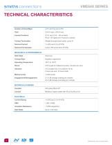
technical characteristics Contact Positions P1/J1 and J1/J2 - 160 contacts P0/J0 - 95 signal and 19 ground contacts Contact Termination Straight through board solder, press fit Nominal Current MECHANICAL & ENVIRONMENTAL Shell Style Contact Style Hypertac hyperboloid Operating Temperature 100 G peak (6 millisecond pulse, 3 shocks per axis) 15 G sweep from 10 to 2000 to 10 Hz 4 hours per axis (12 hours total) Mating Cycles 27.3 LBf average (mating per module) 22.4 LBf average (unmating per module) MATERIALS & FINISHES Insulator Beryllium copper plated with 50 µin Au/50 µin Ni ELECTRICAL Current...
Open the catalog to page 4
Recommended Alignment Fixturing and Tooling alignment tool work instructions Standard VME Backplane J1/J2 press tool Standard VME Backplane J0 press tool Standard VME Polarizing pin press tool Standard VME Daughtercard alignment Standard VME Backplane alignment Backplane Layout
Open the catalog to page 5
Daughter Card Layout
Open the catalog to page 6
smiths connectors OPTION HOLES MATING PLANE •oooooooooooo ooooooooo •oooooooooooo ooooooooo IOOOOOOOOOOOOO OOOOOOOOI •oooooooo oooooooo*
Open the catalog to page 7
smiths connectors KEYING OPTION •oooooooo oooooooo* •oooooooo oooooooo* •oooooooo oooooooo* •oooooooo oooooooo*
Open the catalog to page 8
J0/P0 High Speed Electrical Performance PERFORMANCE Specifications P1/P2 CRD (Contact Resistance at Rated Current) LLCR (Low Level Contact Resistance) Contact Life (Mate / Unmate) Mating Force Demating Force 4.0 hours, 3 axis, 12 hour total 4.0 hours, 3 axis, 12 hour total Test Current Sweep Time No Circuit Interruptions Occurred At 10 Nano second resolution At 10 Nano second resolution Peak Value 3 shock / 3 axis (18 total) 3 shock / 3 axis (18 total) No Circuit Interruptions Occurred At 10 Nano second resolution At 10 Nano second resolution Mechanical Shock Maximum Allowable Gap Between Mating...
Open the catalog to page 9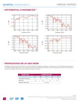
PROPAgATION DELAy AND SKEW Propagation delay through the intrinsic connector assembly is estimated by making a measurement on the reflected signal received on the same broadband fixture that is used to obtain the full vector scattering parameters. In these measurements, there is no inclusion of any other pin lengths other than what is within the intrinsic connector. Skew (ps) Maximum Data Rate2 Notes: 1) Pattern illustrated in the figure on next page was used in the S-parameter and cross talk measurements. 2) Please refer to the full characterization test report for details. Dimensions are in...
Open the catalog to page 10
Differential Pairs Ground With Inclusion of Near End Cross Talk (Aggressor / Victim = 120%) With Inclusion of Near End Cross Talk (Aggressor / Victim = 30%) With Inclusion of Printed Circuit Board VIAs Notes: 1) Pattern illustrated in the figure above was used in the S-parameter and cross talk measurements. 2) Please refer to the full characterization test report for details. Dimensions are in inches [mm]
Open the catalog to page 11
SMITHS CONNECTORS GLOBAL SUPPORT AMERICAS United Kingdom visit us at | smithsconnectors.com | Copyright© 2016 Smiths Connectors | All rights reserved | Version 1.1
Open the catalog to page 12All Smiths Interconnect catalogs and technical brochures
 DaVinci Test Socket Gen V
4 Pages
 QN-Series
2 Pages
 R-Series H-Pin® Socket
2 Pages
 Q-Series H-Pin® Socket
2 Pages
 M-Series H-Pin® Socket
2 Pages
 K Series H-Pin® Socket
2 Pages
 ESJ Series H-Pin Socket
2 Pages
 ES Series H-Pin® Socket
2 Pages
 D Series H-Pin® Socket
2 Pages
 H-Pin Brochure
28 Pages
 C-Series H-Pin® Socket
2 Pages
 ARINC 801
4 Pages
 Optical Backplane Connectors
2 Pages
 Coaxial Couplers Brochure
12 Pages
 Micro-D Twinax
8 Pages
 Micro Quadrax/Twinax Catalog
10 Pages
 Rugged D-Sub
14 Pages
 NDL-T/NDL-Q Miniature Triax
16 Pages
 HYPERGRIP
12 Pages
 Diamond Rf Resistives®
10 Pages
 Lab-Flex® S Series
6 Pages
 Semi-Rigid Cable Brochure
12 Pages
 Planar X RF Filters
4 Pages
 HBB Catalog
36 Pages
 N Series Catalogue
21 Pages
 REP Series Brochure
8 Pages
 KM Series catalog
35 Pages
 KNB/KNC/KND Series Catalog
46 Pages
 HDLP Catalogue
16 Pages
 LightConex Series
5 Pages
 HR CTX Brochure
6 Pages
 Optical FMC Cards
2 Pages
 LightVISION 10G VM Series
2 Pages
 SNAP12
2 Pages
 Volta Series
6 Pages
 K2TVA Series
4 Pages
 TS06 Series
5 Pages
 CTX Series
5 Pages
 CEX Series
9 Pages
 M23 Industrial Catalogue
72 Pages
 Intercompact PCB
8 Pages
 K-Band Passive Components
12 Pages
 BOA Series
8 Pages
 NXS Series
12 Pages
 TSX Fixed Chip Attenuators
4 Pages
 Galileo Test Socket
3 Pages
 HDC Heavy Duty Connectors
42 Pages
 LR Series
52 Pages
 L Series Catalogue
32 Pages
 Thermocouple Spring Probes
4 Pages
 0.020” & 0.030” Centers
7 Pages
 0.156” & 0.187” Centers
5 Pages
 0.050” Centers
12 Pages
 0.187” Centers
5 Pages
 Component Catalog
102 Pages
 SNAP12
2 Pages
 LightVISION VM
2 Pages
 SH-100 & SHE-100 Se
8 Pages
 100563 Coax Series
6 Pages
 SS-30 Series
45 Pages
 Quad-00 Series
4 Pages
 D Series
16 Pages
 Resistor Family
10 Pages
 SpaceNXT™ AURORA Series
8 Pages
 SpaceNXT™ Ku Series
8 Pages
 Interposers
12 Pages
 SpaceNXT™ Q Series
6 Pages
 KuStream 2000 Antenna System
4 Pages
 Dovetail Brochure
4 Pages
 2mm cPCI Catalog
16 Pages
 TT9 SMT Brochure
6 Pages
 Lab-Flex T Series
6 Pages
 Transformer Range Brochure
16 Pages
 TT9 SMT Series Brochure
6 Pages
 B Series Catalogue
24 Pages
 C Series
32 Pages
 C9394
C939436 Pages
 Coax Contacts
7 Pages
 Filters and Diplexers
4 Pages
 K Series Catalogue
76 Pages
 KA series
44 Pages
 M12 Circular W Series
40 Pages
 M23 Stainless Steel
48 Pages
 M40 Circular P Series
16 Pages
 M58 Series Catalog
20 Pages
 MHD Catalog
36 Pages
 Nebula Series
8 Pages
 SCX Coax
9 Pages
 Triax Contacts
13 Pages
 mDCX & mDHC ConneCtorS
9 Pages
 LHS LHZ LHT Series
36 Pages
 Standard coaxial connector
7 Pages
 Eclipta Edge Card Brochure
8 Pages
 Micro Series
7 Pages
 Filter Rack & Panel Catalog
17 Pages
 Filter D-Subminiature Catalogue
18 Pages
 Filter Circular Catalog
24 Pages
 CMD Catalogue
64 Pages
 C150 & C153 CONNECTOR SERIES
36 Pages
 C SERIES sPrinG PrOBes
8 Pages
 LSH Brochure
4 Pages
 LHS Catalogue
23 Pages
 KVPX Brochure
4 Pages
 KS Catalogue
4 Pages
 Hyperstac Datasheet
2 Pages
 HPH Catalogue
24 Pages
 HeavyPower Brochure
6 Pages
 C160 Datasheet
2 Pages
 C128 Datasheet
2 Pages
 C55 Datasheet
2 Pages
 Backplane Twinax Brochure
6 Pages
 KMC Catalogue
25 Pages
 2mm cPCI Brochure
6 Pages
 HPW Catalogue
24 Pages
 HPD & HPF CONNECTOR SERIES
36 Pages
 CMD CONNECTOR SERIES
64 Pages
 Standard Spring Probes
16 Pages
 C153
C15336 Pages
 MIL-DTL-38999 Quadrax/Twinax
10 Pages
 M58 Circular V Series
2 Pages
 M23 Circular S Series
2 Pages
 Circulaires filtrés
24 Pages
 Quadsplitter
8 Pages
 Filtered D-sub connector
18 Pages
 N series
24 Pages


Archived catalogs
 Filtered Adapter
1 Page
 DO Series
2 Pages
 AST
AST2 Pages
 BST
BST5 Pages
 HDC / KDC
23 Pages
 CI-D
CI-D3 Pages
 KLC
KLC6 Pages
 KJB
KJB5 Pages
 CSC
CSC8 Pages
 KB
KB17 Pages
 HD
HD8 Pages
 Single Pole Power Connectors
2 Pages
 Heavy Duty Modular Connectors
25 Pages
 Modular Connectors
27 Pages
 Rack Panel connector
5 Pages
 Single Pole Power Connectors
2 Pages


- Smiths Interconnect data connector
- Smiths Interconnect electrical power supply connector
- Smiths Interconnect metal connector
- Smiths Interconnect round connector
- Smiths Interconnect plastic connector
- Socket electrical connector
- Smiths Interconnect screw-in connector
- Smiths Interconnect industrial connector
- Smiths Interconnect circular connector
- Smiths Interconnect IP67 connector
- Smiths Interconnect rectangular connector
- Male connector
- Current connector
- Smiths Interconnect straight connector
- Smiths Interconnect transceiver
- Optical cable
- Smiths Interconnect RF connector
- Smiths Interconnect electronic filter
- Copper connector