- Catalogs
- Smiths Interconnect
- HDC / KDC
- Company
- Products
- Catalogs
- News & Trends
- Exhibitions
HDC / KDC
1 /23Pages

HDC / KDC
1 /23Pages
Catalog excerpts
HD Series NOVEMBER 2006 1 Signal Connector DIN 41612 • HDC and HDD interchangeable with DIN41612 C and D • 0.6 mm and 1.0 mm Hypertac® contacts, in a two or three row format • Up to 192 positions • HDT style offers mixed arrangements with signal, power and up to 12 co-axial contacts • Accessories include Double Eurocard aligners and plastic covers • HDD Style up to 32 heavy duty 1.0 mm contacts plus a maximum of 16 contacts 0.6 mm dia Applicable Markets: Mil-Aero Space Marine
Open the catalog to page 1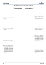
HD Series 2 NOVEMBER 2006 Front release/rear removable contacts Contact insertion Contact removal 1 Assembly Tool Tweezer - Non Ferrous 1 Extraction Tool HPD - 286 0.6 mm male and female contacts and 1 mm male contact. HD240 1 mm female contact 2 Holding main body of extraction tool, align above contact cavity on mating face of insulator 3 Insert tubular tip fully, insuring that tool remains in line with the contact cavity. To avoid damage, do not rotate or exert sideways movement. This will retract contact retention clip ears from engagement with the shoulder in the contact cavity 4 With the...
Open the catalog to page 2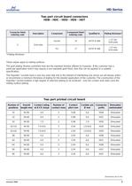
HD Series Two part circuit board connectors HDB - HDC - HDD - HDS - HDT NOVEMBER 2006 3 Dimensions are in mm Connector finish ordering code Description Component Component finish ordering code Qualified to Plating thickness* U Gold plate Socket -/9 ASTM-B-488 1.27 mm Gold plate Pin -/7 ASTM-B-488 1.27 mm Gold plate These values apply to mating surfaces The gold plating finishes published here are the standard finishes offered by Hypertac. If the customer has a particular application which may require a non-standard gold finish, then this can be applied to a suitable specification. The Hypertac©...
Open the catalog to page 3
HD Series All values at s.t.p. unless otherwise stated. The majority of values given are BS Specification or similar, but in all respects the performance is superior. Materials Insulators HDB/C/D/S : Glass reinforced phenolic HDT : Thermoplastic Contacts : Copper alloy Socket wires : Copper alloy Polarising studs : Copper alloy and pins : Nickel plated Signal and Power Contacts Male pin diameter : 0.6mm nominal 1.0mm nominal 3.6mm nominal Contact plating : Refer to Ordering Information Contact resistance 0.6mm contact : 7 milliohms maximum 1.0mm contact : 3 milliohms maximum 3.6mm contact : 1...
Open the catalog to page 4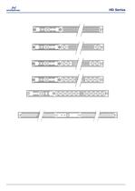
HD Series HDT-96 Position HDT-78 Position + 2 Co-ax/Power cavities HDT-60 Position + 4 Co-ax/power cavities HDT-42 Position + 6 Co-ax/power cavities HDT-6 Position + 10 Co-ax/power cavities HDT-192 Position HDT-156 Position + 4 Co-ax/power cavities HDT-120 Position + Co-ax/power cavities HDT-84 Position + 12 Co-ax/power cavities Specification NOVEMBER 2006 5 Dimensions are in mm
Open the catalog to page 5
HD Series S O L I D I N S U L A T O R 0116 HDT-42 way Signal 6 Coax Male Insulator without DIN aligner 0117 HDT-42 way Signal 6 Coax Female Insulator without DIN aligner 0118 HDT-78 way Signal 2 Coax Male Insulator without DIN aligner 0119 HDT-78 way Signal 2 Coax Female Insulator without DIN aligner 0120 HDT-60 way Signal 4 Coax Male Insulator without DIN aligner 0121 HDT-60 way Signal 4 Coax Female Insulator without DIN aligner 0122 HDT-6 way Signal 10 Coax Male Insulator without DIN aligner 0123 HDT-6 way Signal 10 Coax Female Insulator without DIN aligner X000 - Solder Dipped Terminations...
Open the catalog to page 6
HD Series Row and contact identification NOVEMBER 2006 7 Dimensions are in mm
Open the catalog to page 7
HD Series DIMENSION A DIMENSION B DIMENSION C DIMENSION D HDB/C/D HDS 88.90 93.90 90.00 94.90 48.31 53.26 49.46 54.26 Insulators 8 NOVEMBER 2006 Dimensions are in mm
Open the catalog to page 8
HD Series THREE ROW - STYLE HDT Shrouded Male Half Female Half 88.90 44.45 138.28 max 6.05 1.5 MAX 11.00 14.90 max 14.05 9.30 90.00 43.36 85.35 max 138.28 max 17.28 max 9.3 max 3.55 max 10.50 7.62 15.24 24.14 Insulators NOVEMBER 2006 9 Dimensions are in mm
Open the catalog to page 9
HD Series Insulators NOVEMBER 2006 11 Dimensions are in mm
Open the catalog to page 11
HD Series Panel preparation details Board preparation details 12 NOVEMBER 2006 Dimensions are in mm HDB HDC HDD HDS Dimension A min 8.30 10.80 10.80 8.30 Dimension B min 10.00 12.50 12.50 10.00 Dimension C min 85.00 85.00 85.00 Dimension D min 90.00 90.00 90.00 HDS 38.10 49.40 48.31 HDB 78.74 90.00 88.90 Dimension E Dimension F Dimension G
Open the catalog to page 12
HD Series Board preparation details NOVEMBER 2006 13 Dimensions are in mm
Open the catalog to page 13
HD Series Board preparation details 14 NOVEMBER 2006 Dimensions are in mm N holes: † and ‡ to be increased, when needed, to accept wrap post F, W and Z terminations ‡ to 1.65 dia. min † to 1.20 dia. min
Open the catalog to page 14
HD Series Panel preparation details NOVEMBER 2006 15 Dimensions are in mm † N holes: increase dia. min to 1.20 for termination styles F, W and Z
Open the catalog to page 15
HD Series 7 7 7 Male contact terminations and codes 16 NOVEMBER 2006 Dimensions are in mm Term style Pin dia. Board thickness Dimension A maximum Part number 1st Row 2nd Row 3rd Row B 0.6 mm 1.6 mm 2.75 HD151/7 HD152/7 HD153/7 B 1.0 mm 1.6 mm 2.75 HD154/7 HD155/7 L 0.6 mm 3.2 mm 4.84 HPD685/7 HPD688/7 HPD691/7 Term style Pin dia. Dimension A maximum Part number G 4.15 HD 134/7 P 0.6 mm 6.20 HPD 684/7 N 0.6 mm 14.35 HPD 603/7
Open the catalog to page 16
HD Series Female socket terminations and codes NOVEMBER 2006 17 Dimensions are in mm Term style Pin dia. Dimension A maximum Part number X 0.6 mm 3.97 HPD/522/9 P 0.6 mm 6.00 HD/246/9 P 1.0 mm 6.00 HD/148/9 *Please note When using 1.0 mm pin diameter HDD 032 (Two Row) HDD 042 & 048 (Three Row) up to thirty two 1.0 mm pins will be used. Plus a maximum of sixteen pins 0.6 mm diameter
Open the catalog to page 17
HD Series 18 NOVEMBER 2006 Dimensions are in mm Specification Impedance: 50 Ù Cable group: RG 178 B/U RG 196 A/U Frequency: 0 - 10 GHz Proof Voltage: 750 / 50 Hz Temperature Range: -55° C to +125° C } MIL-SPEC
Open the catalog to page 18
HD Series Power contact - DIN 41626 class 1 NOVEMBER 2006 19 Dimensions are in mm Specification Nominal current: 10 A Cable section: 1.0 mm2 Cable stripping length: 7.50/7.00
Open the catalog to page 19
HD Series Polarising 20 NOVEMBER 2006 Dimensions are in mm
Open the catalog to page 20
HD Series Tooling information NOVEMBER 2006 21 Dimensions are in mm
Open the catalog to page 21All Smiths Interconnect catalogs and technical brochures
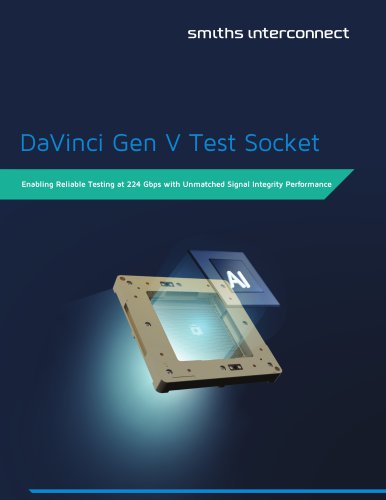 DaVinci Test Socket Gen V
4 Pages
 QN-Series
2 Pages
 R-Series H-Pin® Socket
2 Pages
 Q-Series H-Pin® Socket
2 Pages
 M-Series H-Pin® Socket
2 Pages
 K Series H-Pin® Socket
2 Pages
 ESJ Series H-Pin Socket
2 Pages
 ES Series H-Pin® Socket
2 Pages
 D Series H-Pin® Socket
2 Pages
 H-Pin Brochure
28 Pages
 C-Series H-Pin® Socket
2 Pages
 ARINC 801
4 Pages
 Optical Backplane Connectors
2 Pages
 Coaxial Couplers Brochure
12 Pages
 Micro-D Twinax
8 Pages
 Micro Quadrax/Twinax Catalog
10 Pages
 Rugged D-Sub
14 Pages
 NDL-T/NDL-Q Miniature Triax
16 Pages
 HYPERGRIP
12 Pages
 Diamond Rf Resistives®
10 Pages
 Lab-Flex® S Series
6 Pages
 Semi-Rigid Cable Brochure
12 Pages
 Planar X RF Filters
4 Pages
 HBB Catalog
36 Pages
 N Series Catalogue
21 Pages
 REP Series Brochure
8 Pages
 KM Series catalog
35 Pages
 KNB/KNC/KND Series Catalog
46 Pages
 HDLP Catalogue
16 Pages
 LightConex Series
5 Pages
 HR CTX Brochure
6 Pages
 Optical FMC Cards
2 Pages
 LightVISION 10G VM Series
2 Pages
 SNAP12
2 Pages
 Volta Series
6 Pages
 K2TVA Series
4 Pages
 TS06 Series
5 Pages
 CTX Series
5 Pages
 CEX Series
9 Pages
 M23 Industrial Catalogue
72 Pages
 Intercompact PCB
8 Pages
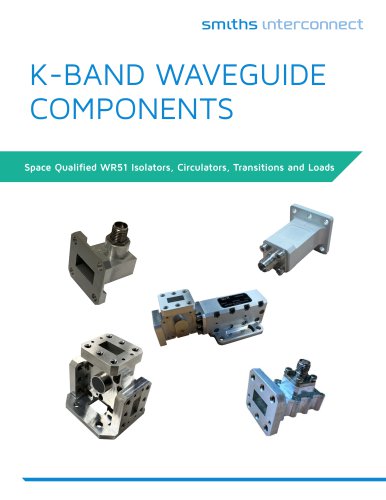
 K-Band Passive Components
12 Pages
 BOA Series
8 Pages
 NXS Series
12 Pages
 TSX Fixed Chip Attenuators
4 Pages
 Galileo Test Socket
3 Pages
 HDC Heavy Duty Connectors
42 Pages
 LR Series
52 Pages
 L Series Catalogue
32 Pages
 Thermocouple Spring Probes
4 Pages
 0.020” & 0.030” Centers
7 Pages
 0.156” & 0.187” Centers
5 Pages
 0.050” Centers
12 Pages
 0.187” Centers
5 Pages
 Component Catalog
102 Pages
 SNAP12
2 Pages
 LightVISION VM
2 Pages
 SH-100 & SHE-100 Se
8 Pages
 100563 Coax Series
6 Pages
 SS-30 Series
45 Pages
 Quad-00 Series
4 Pages
 D Series
16 Pages
 Resistor Family
10 Pages
 SpaceNXT™ AURORA Series
8 Pages
 SpaceNXT™ Ku Series
8 Pages
 Interposers
12 Pages
 SpaceNXT™ Q Series
6 Pages
 KuStream 2000 Antenna System
4 Pages
 Dovetail Brochure
4 Pages
 2mm cPCI Catalog
16 Pages
 TT9 SMT Brochure
6 Pages
 Lab-Flex T Series
6 Pages
 Transformer Range Brochure
16 Pages
 TT9 SMT Series Brochure
6 Pages
 B Series Catalogue
24 Pages
 C Series
32 Pages
 C9394
C939436 Pages
 Coax Contacts
7 Pages
 Filters and Diplexers
4 Pages
 K Series Catalogue
76 Pages
 KA series
44 Pages
 M12 Circular W Series
40 Pages
 M23 Stainless Steel
48 Pages
 M40 Circular P Series
16 Pages
 M58 Series Catalog
20 Pages
 MHD Catalog
36 Pages
 Nebula Series
8 Pages
 SCX Coax
9 Pages
 Triax Contacts
13 Pages
 mDCX & mDHC ConneCtorS
9 Pages
 LHS LHZ LHT Series
36 Pages
 Standard coaxial connector
7 Pages
 Eclipta Edge Card Brochure
8 Pages
 Micro Series
7 Pages
 Filter Rack & Panel Catalog
17 Pages
 Filter D-Subminiature Catalogue
18 Pages
 Filter Circular Catalog
24 Pages
 CMD Catalogue
64 Pages
 C150 & C153 CONNECTOR SERIES
36 Pages
 C SERIES sPrinG PrOBes
8 Pages
 LSH Brochure
4 Pages
 LHS Catalogue
23 Pages
 KVPX Brochure
4 Pages
 KS Catalogue
4 Pages
 Hyperstac Datasheet
2 Pages
 HPH Catalogue
24 Pages
 HeavyPower Brochure
6 Pages
 C160 Datasheet
2 Pages
 C128 Datasheet
2 Pages
 C55 Datasheet
2 Pages
 Backplane Twinax Brochure
6 Pages
 KMC Catalogue
25 Pages
 2mm cPCI Brochure
6 Pages
 VME64X Catalogue
12 Pages
 HPW Catalogue
24 Pages
 HPD & HPF CONNECTOR SERIES
36 Pages
 CMD CONNECTOR SERIES
64 Pages
 Standard Spring Probes
16 Pages
 C153
C15336 Pages
 MIL-DTL-38999 Quadrax/Twinax
10 Pages
 M58 Circular V Series
2 Pages
 M23 Circular S Series
2 Pages
 Circulaires filtrés
24 Pages
 Quadsplitter
8 Pages
 Filtered D-sub connector
18 Pages
 N series
24 Pages


Archived catalogs
 Filtered Adapter
1 Page
 DO Series
2 Pages
 AST
AST2 Pages
 BST
BST5 Pages
 CI-D
CI-D3 Pages
 KLC
KLC6 Pages
 KJB
KJB5 Pages
 CSC
CSC8 Pages
 KB
KB17 Pages
 HD
HD8 Pages
 Single Pole Power Connectors
2 Pages
 Heavy Duty Modular Connectors
25 Pages
 Modular Connectors
27 Pages
 Rack Panel connector
5 Pages
 Single Pole Power Connectors
2 Pages


- Smiths Interconnect data connector
- Smiths Interconnect electrical power supply connector
- Smiths Interconnect metal connector
- Smiths Interconnect round connector
- Smiths Interconnect plastic connector
- Socket electrical connector
- Smiths Interconnect screw-in connector
- Smiths Interconnect industrial connector
- Smiths Interconnect circular connector
- Smiths Interconnect IP67 connector
- Smiths Interconnect rectangular connector
- Male connector
- Current connector
- Smiths Interconnect straight connector
- Smiths Interconnect transceiver
- Optical cable
- Smiths Interconnect RF connector
- Smiths Interconnect electronic filter
- Copper connector