
- Catalogs
- Smiths Interconnect
- CMD Catalogue


- Company
- Products
- Catalogs
- News & Trends
- Exhibitions
CMD Catalogue

CMD Catalogue
Catalog excerpts

CONNECTOR SERIES PCB Connectors
Open the catalog to page 1
HYPERBOLOID TECHNOLOGY Smiths Connectors offers an extensive range of superior contact technologies suitable for standard and custom solutions. Hypertac® (HYPERboloid conTACT) is the original superior performing hyperboloid contact technology designed for use in all applications and in harsh and demanding environments where high reliability and safety are critical. The inherent electrical and mechanical characteristics of the Hypertac hyperboloid contact ensures unrivalled performance in terms of reliability, number of mating cycles, low contact force and minimal contact resistance. The shape...
Open the catalog to page 2
1. SCOPE 1.1 Scope This Design covers CMD Connectors Family, plug and receptacle style, with 42, 82, 110, 126, 158, 174, 220, 236 and 316 pin or socket contact positions, conforming to MIL-C-55302. Contact arrangement is offset-grid pattern within dielectric connector body with four rows, .075 in (1.905 mm) center-to-center contact spacing in each row, and .075 in (1.905 mm) row-to-row spacing. Contact size is 0.6 mm nominal pin DIA.Polarization feature is incorporated in each connector assembly to assure correct insertion. Coding key system provides 36 possible keying combinations. There are...
Open the catalog to page 4
2. APPLIED DOCUMENTS 2.1 Applied documents CMD Connectors Family is designed, manufactured, tested and delivered in accordance with the documents listed below. The latest issue of the following documents, documents amendments and notices, in being on 30 June 1994 are used unless otherwise specified in this Design. MIL-C-26074 Coatings, electroless nickel requirement for. MIL-I-46058 Insulating compound, electrical (for coating printed circuit assemblies). MIL-P-50884 Printed-wiring, flexible and rigid-flex. MIL-C-55302 Connectors, printed circuit subassembly and accessories. MIL-I-81550 Insulating...
Open the catalog to page 5
3.3 Socket contact and contact terminal Socket contact is HYPERTAC and contact terminal types are: dip solder, (straight and right angle), wire wrappost, surface mount tail, and crimp. 3.3.1 Socket contact materials HYPERTAC springs are wiredrawn from beryllium-copper alloy per QQ-C-530, (ASTM B197). Socket contact body is screw machined from copper-alloy per QQ-B-626, (ASTM B16). Protective finishing is gold plate, over suitable underplate, as specified in MIL-C-55302. 3.3.2 Dip solder, (straight and right angle), wire wrappost, and crimp socket contact terminals are screw machined, one-piece...
Open the catalog to page 6
3.6 CMD Connectors Family requirements are: - contact engagement and separation forces: maximum engagement force =100 g (3.53 oz); minimum separation force =14 g (.49 oz); - connector mating and unmating forces: maximum mating force =60 g (2.12 oz) multiplied by number of contacts;minimum unmating force =20 g (.71 oz) multiplied by number of contacts; - contact current rating: the connector may have any combination of current flow and ambient temperature provided the contact or connector temperature does not exceed 125 °C. If mated plug and receptacle connectors are both equipped with dip solder,...
Open the catalog to page 7
BODY CONNECTOR DIMENSIONS Connector figure (mating face) Applicable to plug connector body equipped with dip solder, straight thru, contact terminal. Applicable to plug connector body equipped with all the other contact terminal styles.
Open the catalog to page 8
Contact terminal types available are: Contact positions Connector style Surface mount tail Wire wrap post (Straight thru) (Right angle) Plug connector pin contacts equipped Check Firm Receptacle connector socket contacts equipped Check Firm Plug connector pin contacts equipped Check Firm Receptacle connector socket contacts equipped Check Firm Plug connector pin contacts equipped Receptacle connector socket contacts equipped Plug connector pin contacts equipped Check Firm Receptacle connector socket contacts equipped Check Firm Plug connector pin contacts equipped Receptacle connector socket...
Open the catalog to page 9
CMD PLUG CONNECTOR: 42, 82, 110, 126, 158 AND 174 PIN CONTACT POSITIONS PLUG CONNECTOR: 42, 82, 110, 126, 158 and 174 PIN CONTACT POSITIONS, .075 INCH SPACING (1.905 mm), DIP SOLDER (RIGHT ANGLE) TERMINAL STYLE A max B D-shaped guide pins MOUNTING PATTERN, DAUGHTERBOARD APPLICATION, (RECOMMENDED PCB HOLE CONFIGURATION) COMPONENT SIDE Ø 0.70 min Last hole position 4.00 Last contact posi
Open the catalog to page 10
CMD PLUG CONNECTOR: 42, 82, 110, 126, 158 and 174 PIN CONTACT POSITIONS table I Weight* in grams (with g=9.81 m/s2) Contact positions Contact positions * According to contacts terminal length, and with D-shaped guide pins installed NOTES 1. Dimensions for user installation purpose only. 2. Dimensions are in millimeters. 3. Dimensions in width of these connectors are specified in the table I of this page. 4. Materials, finishes and connectors requirements are described into this catalog. Hot solder dipping,as dip solder terminal end finishing, is available at Customer request, (please consult...
Open the catalog to page 11
1 connector family 2 connector size 5 contact terminal style Dip solder, right angle, with: A .109 inch (2.76 mm) long dip Y D-shaped guide pins P universal coupling guide pins (for test type connectors) 0 0 When D-shaped guide pins are installed in the 01 polarized position, (see polarization configuration chart on page 44), without Loctite 242 applied. 0 1 to 3 6 When D-shaped guide pins are installed in the proper polarized position and Loctite 242 is applied to the threads, (see polarization configuration chart on page 44). 3 7 When universal coupling guide pins, (for test type connectors),...
Open the catalog to page 12
CMD PLUG CONNECTOR: 42, 82, 110, 126, 158 and 174 PIN CONTACT POSITIONS PLUG CONNECTOR: 42, 82, 110, 126, 158 and 174 PIN CONTACT POSITIONS, .075 INCH SPACING (1.905 mm), DIP SOLDER (STRAIGHT) TERMINAL STYLE A max 4.00 Last contact position D-shaped guide pins MOUNTING PATTERN, IN PARALLEL ARRANGEMENT BOARD-TO-BOARD CONNECTION, (RECOMMENDED PCB HOLE CONFIGURATION) COMPONENT SIDE Ø 0.70 min = LAST HOLE POSITION
Open the catalog to page 13
CMD PLUG CONNECTOR: 42, 82, 110, 126, 158 and 174 CONTACT POSITIONS table I Weight* in grams (with g=9.81 m/s2) Contact positions Contact positions * According to contacts terminal length, and with D-shaped guide pins installed NOTES 1. Dimensions for User installation purpose only. 2. Dimensions are in millimeters. 3. Dimensions in width of these connectors are specified in the table I of this page. 4. Materials, finishes and connectors requirements are described into this catalog. Hot solder dipping,as dip solder terminal end finishing, is available at Customer request, (please consult the...
Open the catalog to page 14All Smiths Interconnect catalogs and technical brochures
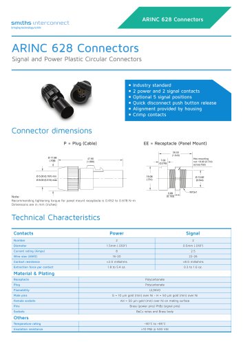 Arinc 628 Connectors
2 Pages
 DaVinci Test Socket Gen V
4 Pages
 QN-Series
2 Pages
 R-Series H-Pin® Socket
2 Pages
 Q-Series H-Pin® Socket
2 Pages
 M-Series H-Pin® Socket
2 Pages
 K Series H-Pin® Socket
2 Pages
 ESJ Series H-Pin Socket
2 Pages
 ES Series H-Pin® Socket
2 Pages
 D Series H-Pin® Socket
2 Pages
 H-Pin Brochure
28 Pages
 C-Series H-Pin® Socket
2 Pages
 ARINC 801
4 Pages
 Optical Backplane Connectors
2 Pages
 Coaxial Couplers Brochure
12 Pages
 Micro-D Twinax
8 Pages
 Micro Quadrax/Twinax Catalog
10 Pages
 Rugged D-Sub
14 Pages
 NDL-T/NDL-Q Miniature Triax
16 Pages
 HYPERGRIP
12 Pages
 Diamond Rf Resistives®
10 Pages
 Lab-Flex® S Series
6 Pages
 Semi-Rigid Cable Brochure
12 Pages
 Planar X RF Filters
4 Pages
 HBB Catalog
36 Pages
 N Series Catalogue
21 Pages
 REP Series Brochure
12 Pages
 KM Series catalog
35 Pages
 KNB/KNC/KND Series Catalog
46 Pages
 HDLP Catalogue
16 Pages
 LightConex Series
5 Pages
 HR CTX Brochure
6 Pages
 Optical FMC Cards
2 Pages
 LightVISION 10G VM Series
2 Pages
 SNAP12
2 Pages
 Volta Series
6 Pages
 K2TVA Series
4 Pages
 TS06 Series
5 Pages
 CTX Series
5 Pages
 CEX Series
9 Pages
 M23 Industrial Catalogue
72 Pages
 Intercompact PCB
8 Pages
 K-Band Passive Components
12 Pages
 BOA Series
8 Pages
 NXS Series
12 Pages
 TSX Fixed Chip Attenuators
4 Pages
 Galileo Test Socket
3 Pages
 HDC Heavy Duty Connectors
42 Pages
 LR Series
52 Pages
 L Series Catalogue
53 Pages
 Thermocouple Spring Probes
4 Pages
 0.020” & 0.030” Centers
7 Pages
 0.156” & 0.187” Centers
5 Pages
 0.050” Centers
12 Pages
 0.187” Centers
5 Pages
 Component Catalog
102 Pages
 SNAP12
2 Pages
 LightVISION VM
2 Pages
 SH-100 & SHE-100 Se
8 Pages
 100563 Coax Series
6 Pages
 SS-30 Series
45 Pages
 D Series
16 Pages
 Resistor Family
10 Pages
 SpaceNXT™ AURORA Series
8 Pages
 SpaceNXT™ Ku Series
8 Pages
 Interposers
12 Pages
 SpaceNXT™ Q Series
6 Pages
 KuStream 2000 Antenna System
4 Pages
 Dovetail Brochure
4 Pages
 2mm cPCI Catalog
16 Pages
 TT9 SMT Brochure
6 Pages
 Lab-Flex T Series
6 Pages
 Transformer Range Brochure
16 Pages
 TT9 SMT Series Brochure
6 Pages
 B Series Catalogue
24 Pages
 C Series
32 Pages
 C9394
C939436 Pages
 Coax Contacts
7 Pages
 Filters and Diplexers
4 Pages
 K Series Catalogue
76 Pages
 KA series
44 Pages
 M12 Circular W Series
40 Pages
 M23 Stainless Steel
48 Pages
 M40 Circular P Series
16 Pages
 MHD Catalog
36 Pages
 Nebula Series
8 Pages
 SCX Coax
9 Pages
 Triax Contacts
13 Pages
 mDCX & mDHC ConneCtorS
9 Pages
 LHS LHZ LHT Series
36 Pages
 Standard coaxial connector
7 Pages
 Eclipta Edge Card Brochure
8 Pages
 Micro Series
7 Pages
 Filter Rack & Panel Catalog
17 Pages
 Filter D-Subminiature Catalogue
18 Pages
 Filter Circular Catalog
24 Pages
 C150 & C153 CONNECTOR SERIES
36 Pages
 C SERIES sPrinG PrOBes
8 Pages
 LSH Brochure
4 Pages
 LHS Catalogue
23 Pages
 KVPX Brochure
4 Pages
 KS Catalogue
4 Pages
 Hyperstac Datasheet
2 Pages
 HPH Catalogue
24 Pages
 HeavyPower Brochure
16 Pages
 C160 Datasheet
2 Pages
 C128 Datasheet
2 Pages
 C55 Datasheet
2 Pages
 Backplane Twinax Brochure
6 Pages
 KMC Catalogue
25 Pages
 2mm cPCI Brochure
6 Pages
 VME64X Catalogue
12 Pages
 HPW Catalogue
24 Pages
 HPD & HPF CONNECTOR SERIES
36 Pages
 CMD CONNECTOR SERIES
64 Pages
 C153
C15336 Pages
 MIL-DTL-38999 Quadrax/Twinax
10 Pages
 M23 Circular S Series
2 Pages
 Circulaires filtrés
24 Pages
 Quadsplitter
8 Pages
 Filtered D-sub connector
18 Pages
 N series
24 Pages











Archived catalogs
 Filtered Adapter
1 Page
 DO Series
2 Pages
 AST
AST2 Pages
 BST
BST5 Pages
 HDC / KDC
23 Pages
 CI-D
CI-D3 Pages
 KLC
KLC6 Pages
 KJB
KJB5 Pages
 CSC
CSC8 Pages
 KB
KB17 Pages
 HD
HD8 Pages
 Single Pole Power Connectors
2 Pages
 Heavy Duty Modular Connectors
25 Pages
 Modular Connectors
27 Pages
 Rack Panel connector
5 Pages
 Single Pole Power Connectors
2 Pages


- Electrical cable
- Smiths Interconnect data connector
- Smiths Interconnect electrical power supply connector
- Copper cable
- Smiths Interconnect metal connector
- Copper electrical cable
- Smiths Interconnect circular connector
- Smiths Interconnect plastic connector
- Smiths Interconnect screw-in connector
- Socket electrical connector
- Smiths Interconnect industrial connector
- Smiths Interconnect IP67 connector
- Smiths Interconnect rectangular connector
- Male connector
- Current connector
- Smiths Interconnect straight connector
- Smiths Interconnect cable harness
- Smiths Interconnect RF connector
- Smiths Interconnect transceiver