- Company
- Products
- Catalogs
- News & Trends
- Exhibitions
CI-D

CI-D
- The CI-D Series connectors feature a two-contact row layout with a 5.08 mm center-to-center spacing and a nominal pin diameter of 1.5 mm. They are available in 11 to 47 contact positions with right angle, straight through, and solder cup termination styles.
- These connectors are designed to withstand high shock and vibration, conforming to NF-C 93 421 and HE704 general requirements, making them suitable for industrial and mass transit applications.
- Special versions with 23, 29, and 47 ways are available in thermoplastic material upon request.
- Contact Number: 11 to 47
- Contact Diameter: 1.5 mm nominal
- Current Rating: 8A
- Contact Life Cycle: >100,000 cycles
- Dielectric Withstanding Voltage: 2000 VRMS at sea level
- Temperature Range: -55 °C to +125 °C
- Insulation Resistance: >106 MΩ at 500 V d.c.
- Insulator Material: DAP 5553 blue / PE (special version)
- Contact Material: Brass with Gold Plating
- Contact Resistance: ≤2.5 mΩ
- Plating conforms to MIL-DTL-55302 standards.
- Connector family includes various sizes and contact arrangements, with options for right angle, straight through, and solder cup terminal styles.
- Mounting styles and dimensions are specified for different terminal styles, with detailed measurements provided for both plug and receptacle configurations.
- All dimensions are provided in millimeters, with detailed diagrams illustrating the layout and mounting specifications for both plug and receptacle components.
Catalog excerpts

CI-D Series APRIL 2005 33 Technical Characteristics 2 Contact Row PCB to Cable Connectors • Offset grid contact layout, two contact rows within dielectric connector body, 5.08 mm center-to-center contact spacing. • 1.5 mm nominal pin DIA contact size; 11 to 47 contact positions; right angle, straight thru and solder cup termination styles. • High shock and vibration proof. • Conforms to NF-C 93 421, HE704 general requirements. • For Industrial and Mass Transit applications. • 23, 29, 47 ways available in thermoplastic material as special version (ask to the factory) Contact Number Contact Diameter Current Rating Contact Life Cycle Dielectric Withstanding Voltage Temperature Range Insulation Resistance Insulator Contact Plating - Material - Plating Contact Resistance 11 to 47 1.5 mm nominal pin DIA 8A >100000 2000 VRMS – sea level -55 °C to +125 °C >106 MÙ at 500 V d.c. DAP 5553 blue / PE (special version) Brass Gold 2.5 mÙ
Open the catalog to page 1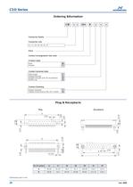
CI-D Series Plug Receptacle 11 17 23 29 35 46.00 38.96 54.2 61.25 76.5 69.44 84.68 91.7 99.92 106.95 41 47 122.2 137.3 115.16 130.4 A B No of contact A 11.00 4,14 4.00 2.54 3.50 5.08 Ø 2.50 11.60 B 9.20 10.70 3.00 A B 4.14 2.54 2 4 6... 1 3 5... 11.00 Plug & Receptacle 34 APRIL 2005 Dimensions are in mm CID * * 254 B * * * 11, 17, 23, 29, 35, 41, 47 Plating standard Plating conforming to MIL-DTL-55302 Connector family Connector size Contact finishing Pitch Contact arrangement: two rows Right angle Straight through Straight through (only for receptacle) Solder cup MF Contact style Male Female...
Open the catalog to page 2
Mounting styles Mounting dimensions CI-D Series 6.35 Ø2.00 Ø1.60 hole Ref. S Up to 16 AWG Ø1.00 6.65 Ref. A 10.80 Ø1.00 Ref. D 7.10 3.60 3.80 5.08 Ø 1.00 Ref. C Plug For receptacle with terminal style S Ø 5.20 Ø 2.70 90° For plug with terminal style C For receptacle with terminal style A and D B D 4.14 5.08 B C No of contact D 11 17 23 29 35 41 47 33 38.96 109 69.44 115.16 48 54.2 63.40 84.68 78.70 99.92 94 124 130.4 25.40 40.64 55.88 71.12 86.36 101.60 116.84 Mother Board Contact No 1 Ø 3.20 2Holes Ø 1.20 2.54 C B 0.640 Daughter Board B C 2.54 Ø 2.70 2Holes Ø 1.20 Contact No 1 Ø 3.2 2Holes 11...
Open the catalog to page 3All Smiths Interconnect catalogs and technical brochures
 DaVinci Test Socket Gen V
4 Pages
 QN-Series
2 Pages
 R-Series H-Pin® Socket
2 Pages
 Q-Series H-Pin® Socket
2 Pages
 M-Series H-Pin® Socket
2 Pages
 K Series H-Pin® Socket
2 Pages
 ESJ Series H-Pin Socket
2 Pages
 ES Series H-Pin® Socket
2 Pages
 D Series H-Pin® Socket
2 Pages
 H-Pin Brochure
28 Pages
 C-Series H-Pin® Socket
2 Pages
 ARINC 801
4 Pages
 Optical Backplane Connectors
2 Pages
 Coaxial Couplers Brochure
12 Pages
 Micro-D Twinax
8 Pages
 Micro Quadrax/Twinax Catalog
10 Pages
 Rugged D-Sub
14 Pages
 NDL-T/NDL-Q Miniature Triax
16 Pages
 HYPERGRIP
12 Pages
 Diamond Rf Resistives®
10 Pages
 Lab-Flex® S Series
6 Pages
 Semi-Rigid Cable Brochure
12 Pages
 Planar X RF Filters
4 Pages
 HBB Catalog
36 Pages
 N Series Catalogue
21 Pages
 REP Series Brochure
8 Pages
 KM Series catalog
35 Pages
 KNB/KNC/KND Series Catalog
46 Pages
 HDLP Catalogue
16 Pages
 LightConex Series
5 Pages
 HR CTX Brochure
6 Pages
 Optical FMC Cards
2 Pages
 LightVISION 10G VM Series
2 Pages
 SNAP12
2 Pages
 Volta Series
6 Pages
 K2TVA Series
4 Pages
 TS06 Series
5 Pages
 CTX Series
5 Pages
 CEX Series
9 Pages
 M23 Industrial Catalogue
72 Pages
 Intercompact PCB
8 Pages
 K-Band Passive Components
12 Pages
 BOA Series
8 Pages
 NXS Series
12 Pages
 TSX Fixed Chip Attenuators
4 Pages
 Galileo Test Socket
3 Pages
 HDC Heavy Duty Connectors
42 Pages
 LR Series
52 Pages
 L Series Catalogue
32 Pages
 Thermocouple Spring Probes
4 Pages
 0.020” & 0.030” Centers
7 Pages
 0.156” & 0.187” Centers
5 Pages
 0.050” Centers
12 Pages
 0.187” Centers
5 Pages
 Component Catalog
102 Pages
 SNAP12
2 Pages
 LightVISION VM
2 Pages
 SH-100 & SHE-100 Se
8 Pages
 100563 Coax Series
6 Pages
 SS-30 Series
45 Pages
 Quad-00 Series
4 Pages
 D Series
16 Pages
 Resistor Family
10 Pages
 SpaceNXT™ AURORA Series
8 Pages
 SpaceNXT™ Ku Series
8 Pages
 Interposers
12 Pages
 SpaceNXT™ Q Series
6 Pages
 KuStream 2000 Antenna System
4 Pages
 Dovetail Brochure
4 Pages
 2mm cPCI Catalog
16 Pages
 TT9 SMT Brochure
6 Pages
 Lab-Flex T Series
6 Pages
 Transformer Range Brochure
16 Pages
 TT9 SMT Series Brochure
6 Pages
 B Series Catalogue
24 Pages
 C Series
32 Pages
 C9394
C939436 Pages
 Coax Contacts
7 Pages
 Filters and Diplexers
4 Pages
 K Series Catalogue
76 Pages
 KA series
44 Pages
 M12 Circular W Series
40 Pages
 M23 Stainless Steel
48 Pages
 M40 Circular P Series
16 Pages
 M58 Series Catalog
20 Pages
 MHD Catalog
36 Pages
 Nebula Series
8 Pages
 SCX Coax
9 Pages
 Triax Contacts
13 Pages
 mDCX & mDHC ConneCtorS
9 Pages
 LHS LHZ LHT Series
36 Pages
 Standard coaxial connector
7 Pages
 Eclipta Edge Card Brochure
8 Pages
 Micro Series
7 Pages
 Filter Rack & Panel Catalog
17 Pages
 Filter D-Subminiature Catalogue
18 Pages
 Filter Circular Catalog
24 Pages
 CMD Catalogue
64 Pages
 C150 & C153 CONNECTOR SERIES
36 Pages
 C SERIES sPrinG PrOBes
8 Pages
 LSH Brochure
4 Pages
 LHS Catalogue
23 Pages
 KVPX Brochure
4 Pages
 KS Catalogue
4 Pages
 Hyperstac Datasheet
2 Pages
 HPH Catalogue
24 Pages
 HeavyPower Brochure
6 Pages
 C160 Datasheet
2 Pages
 C128 Datasheet
2 Pages
 C55 Datasheet
2 Pages
 Backplane Twinax Brochure
6 Pages
 KMC Catalogue
25 Pages
 2mm cPCI Brochure
6 Pages
 VME64X Catalogue
12 Pages
 HPW Catalogue
24 Pages
 HPD & HPF CONNECTOR SERIES
36 Pages
 CMD CONNECTOR SERIES
64 Pages
 Standard Spring Probes
16 Pages
 C153
C15336 Pages
 MIL-DTL-38999 Quadrax/Twinax
10 Pages
 M58 Circular V Series
2 Pages
 M23 Circular S Series
2 Pages
 Circulaires filtrés
24 Pages
 Quadsplitter
8 Pages
 Filtered D-sub connector
18 Pages
 N series
24 Pages


Archived catalogs
 Filtered Adapter
1 Page
 DO Series
2 Pages
 AST
AST2 Pages
 BST
BST5 Pages
 HDC / KDC
23 Pages
 KLC
KLC6 Pages
 KJB
KJB5 Pages
 CSC
CSC8 Pages
 KB
KB17 Pages
 HD
HD8 Pages
 Single Pole Power Connectors
2 Pages
 Heavy Duty Modular Connectors
25 Pages
 Modular Connectors
27 Pages
 Rack Panel connector
5 Pages
 Single Pole Power Connectors
2 Pages


- Smiths Interconnect data connector
- Smiths Interconnect electrical power supply connector
- Smiths Interconnect metal connector
- Smiths Interconnect circular connector
- Smiths Interconnect plastic connector
- Socket electrical connector
- Smiths Interconnect screw-in connector
- Smiths Interconnect industrial connector
- Smiths Interconnect IP67 connector
- Smiths Interconnect rectangular connector
- Male connector
- Current connector
- Smiths Interconnect straight connector
- Smiths Interconnect transceiver
- Optical cable
- Smiths Interconnect RF connector
- Smiths Interconnect electronic filter
- Copper connector
- Smiths Interconnect cable harness