- Products
- Catalogs
- News & Trends
- Exhibitions
VF
1 /60Pages

VF
1 /60Pages
Catalog excerpts
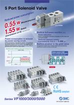
5 Port Solenoid Valve duced Re Built-in full-wave rectifier (AC) Noise Power consumption is reduced by power saving circuit. Power consumption is decreased by approx. 1/3 by reducing the wattage required to hold the valve in an energized state. (Effective energizing time is over 40 ms at 24 VDC.) Refer to electrical power waveform as shown below. Noise is considerably reduced by changing it to DC mode with a full-wave rectifier. apparent power Conventional: 5.6 VA → 1.55 VA Built-in strainer in the pilot valve Unexpected troubles due to foreign matter can be prevented. Note) Be sure to mount an air filter on the inlet side. Electrical power waveform with power saving circuit Applied voltage Rubber material: HNBR Ozone-resistant specification (The pilot valve poppet is made of FKM.) With power saving circuit RoHS compliant Series VF1000/3000/5000
Open the catalog to page 1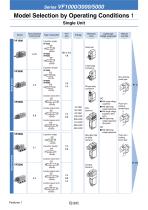
Model Selection by Operating Conditions 1 Single Unit Sonic conductance Electrical Light/surge Manual entry voltage suppressor override L-type plug M-type plug ■ With surge voltage voltage suppressor ■ With surge voltage voltage suppressor voltage suppressor push type slotted type lever type
Open the catalog to page 2
Model Selection by Operating Conditions 2 Manifold Series Manifold base model Applicable valve Applicable stations Body ported Base mounted
Open the catalog to page 3
Cylinder Speed Chart 1 This chart is provided as guidelines only. For performance under various conditions, use SMC’s Model Selection Program before making a judgement. Body Ported Bore size Series CJ2 Average Pressure 0.5 MPa speed Load factor 50% (mm/s) Stroke 60 mm Series CS1 Pressure 0.5 MPa Load factor 50% Stroke 1000 mm Series MB, CA2 Pressure 0.5 MPa Load factor 50% Stroke 500 mm Series CM2 Pressure 0.5 MPa Load factor 50% Stroke 300 mm Note) With Perpendicular, upward actuation Horizontal actuation : when using steel piping Base Mounted Bore size Series CJ2 Average Pressure 0.5 MPa speed...
Open the catalog to page 4
Cylinder Speed Chart 2 This chart is provided as guidelines only. For performance under various conditions, use SMC’s Model Selection Program before making a judgement. Conditions Body Ported Body ported Tube bore x Length Speed controller Tube bore x Length Speed controller Tube bore x Length Speed controller Body Ported [when using SGP (Steel Piping)] Body ported Tube bore x Length Speed controller Base Mounted Base mounted Tube bore x Length Speed controller Tube bore x Length Speed controller Base Mounted [when using SGP (Steel Piping)] Base mounted Tube bore x Length Speed controller Tube...
Open the catalog to page 5
Pilot Operated 5 Port Solenoid Valve Series VF1000/3000/5000 Single Unit Body Ported Note) Only DIN and conduit terminal types are available with AC mode. Refer to the electrical entry for details. How to Order Valve Body ported Series 1 3 5 2-position single 2-position double 3-position closed centre 3-position exhaust centre 3-position pressure centre Without bracket With bracket Note) M5 is available with Nil only. Body model (The bracket cannot be connected after delivered.) Pressure specification Standard (0.7 MPa) High-pressure type (1 MPa) Coil specification Body option — 0: Pilot valve...
Open the catalog to page 6
Pilot Operated 5 Port Solenoid Valve Body Ported/Single Unit Specifications Model Fluid Operating pressure range (MPa) Air 2-position single/3-position 0.15 to 0.7 Standard 2-position double 0.1 to 0.7 High2-position single/3-position 0.15 to 1.0 pressure 2-position double type 0.1 to 1.0 Ambient and fluid temperature (°C) –10 to 50 (No freezing) 10 10 5 2-position single/double Max. operating frequency (Hz) — 3 3 3-position Non-locking push type Push-turn locking slotted type Manual override Push-turn locking lever type Individual exhaust, Main/Pilot valve common exhaust (Except VF1000) Pilot...
Open the catalog to page 7
Series VF1000/3000/5000 Flow-rate Characteristics/Weight Flow-rate characteristics Note 1) Port size Valve model Q [l/min] C [dm3/ (ANR) Note 3) (s/bar)] Double Closed centre Single Double Single Double Q [l/min] (ANR) Note 3) Grommet DIN terminal Pressure centre Closed centre Pressure centre Closed centre Pressure centre Closed centre Exhaust centre 3position Pressure centre Note 1) [ ]: Normal position Note 2) Values without bracket Note 3) These valves have been calculated according to ISO6358 and indicate the flow rate under standard conditions with an inlet pressure of 0.6 MPa (relative...
Open the catalog to page 8
Pilot Operated 5 Port Solenoid Valve Body Ported/Single Unit Construction/Body Ported 2-position single 2-position double Symbol 2-position double 3-position closed centre/exhaust centre/pressure centre Symbol (Drawing shows a closed centre type.) 3-position pressure centre Description Body Spool valve Note White Adapter plate Material Aluminum die-casted Aluminum die-casted (VF5000: Resin) Resin Aluminum, HNBR Stainless steel Pilot valve assembly Refer to “How to Order Pilot Valve Assembly” on page 5. Built-in strainer Bracket Assembly Part No. Description Bracket (for VF1000/3000 single) Note)...
Open the catalog to page 9
Series VF1000/3000/5000 How to Order Pilot Valve Assembly Caution When only the pilot valve assembly is replaced, it is not possible to change from V211 (Grommet or L/M-type) to V212 (DIN or Conduit type), or vice versa. Valve model: Note) Select from the below in accordance with the valve used. 5 G Z Light/surge voltage suppressor — Without light/surge voltage suppressor With surge voltage suppressor With light/surge voltage suppressor With surge voltage suppressor (Non-polar) With light/surge voltage suppressor (Non-polar) V211 Pilot valve assembly Note) When T is selected, only Z type of light/surge...
Open the catalog to page 10
Pilot Operated 5 Port Solenoid Valve Body Ported/Single Unit Series VF1000/Body Ported/Dimensions 2-position single Grommet (G) (H): VF1120- G -M5 (-F) H Manual override 2 x M4 x 0.7 thread depth 5 (For mounting) (Lead wire length) (Indicator light) DC without light/surge voltage suppressor 6 L-type plug connector (L): VF1120-L- M5 (-F) 01 (Lead wire length) Manual override (Lead wire length) Applicable cable O.D. ø4.5 to ø7 Approx. 300 (Lead wire length) Unless otherwise indicated, dimensions are the same as Grommet (G). Conduit terminal (T): VF1120-T- M5 (-F) 01 Max. 10 Applicable cable O.D....
Open the catalog to page 11All SMC catalogs and technical brochures
 In-line Type Vacuum Ejector
6 Pages
 Serie HRR
64 Pages
 Série VP/VG
33 Pages
 Série XL
27 Pages
 Série ACG/ARG/AWG
45 Pages
 Série JXC5H/6H
36 Pages
 LEJS100-X400 series
15 Pages
 JMB series
13 Pages
 JCM series
21 Pages
 PF3A7*H
40 Pages
 PF3W
PF3W34 Pages
 Compact Guide Cylinder with Lock
36 Pages
 Water Treatment
16 Pages
 Food & Packaging Industry
4 Pages
 Digital Gap Checker
26 Pages
 Vacuum Pad
16 Pages
 One-touch Fittings
224 Pages
 Soft Start-up Valve
16 Pages
 Electric Actuator
272 Pages
 Rotary Actuator
40 Pages
 Compact Guide Cylinder
18 Pages
 Compact Slide
24 Pages
 Air Cylinder
124 Pages
 LEFB, LEFG-BS series
180 Pages
 JMGP series
16 Pages
 ISO Cylinder
32 Pages
 IZD10
IZD1020 Pages
 IZH10
IZH108 Pages
 Fan Type Lonizer
28 Pages
 Check Valves
4 Pages
 Compact Cylinder/Clean series
16 Pages
 3 port solenoid Valve
74 Pages
 Vacuum Ejector Series ZM
20 Pages
 Series ZL
20 Pages
 Series CM2
92 Pages
 Series IDGA/IDG
56 Pages
 Platform Cylinder Series CXT
14 Pages
 IDH-A
IDH-A12 Pages
 CP96-C96-B
74 Pages
 CVQ
CVQ24 Pages
 HY
HY52 Pages
 VNA
VNA10 Pages
 Series MXY
28 Pages
 Series MXP
39 Pages
 Air Slide Table
132 Pages
 Compact Cylinder Series CQ2
138 Pages
 S0700
S0700112 Pages
 SYJ
SYJ96 Pages
 SY - NEW
164 Pages
 C(D)55 series
24 Pages
 C(D)Q2 series
216 Pages
 MGP series
36 Pages
 11-LEFS series
19 Pages
 LECS series
16 Pages
 LECPA series
4 Pages
 KQ series
80 Pages
 IDF series
16 Pages
 ZP series
69 Pages
 MHF series
32 Pages
 MHZ series
68 Pages
 CRB series
44 Pages
 MGJ series
7 Pages
 AC series
98 Pages
 VH series
14 Pages
 LVA series
43 Pages
 VDW series
28 Pages
 LVM series
28 Pages
 VX2 series
32 Pages
 MXH series
32 Pages
 MXF series
12 Pages
 CXW series
48 Pages
 CXS series
76 Pages
 CQS series
40 Pages
 CQM series
28 Pages
 CLQ series
36 Pages


