- Products
- Catalogs
- News & Trends
- Exhibitions
Soft Start-up Valve
1 /16Pages

Soft Start-up Valve
1 /16Pages
Catalog excerpts
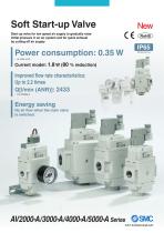
Soft Start-up Valve Start-up valve for low speed air supply to gradually raise initial pressure in an air system and for quick exhaust by cutting off air supply New C € crqhs) Power consumption: 0.35 W * At 12/24 V DC Current model: 1.8 W (80 % reduction) Improved flow rate characteristics: Up to 2.2 times Q[l/min (ANR)]: 2433 Energy saving No air flow when the main valve is switched.
Open the catalog to page 1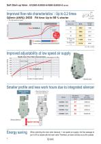
Soft Start-up Valve AV2000-A/3000-A/4000-A/5000-A Series ∗1 Improved flow rate characteristics : Up to 2.2 times Q[l/min (ANR)]: 2433 Fill time: Up to 50 % shorter ∗1 For high speed air supply Body size Current model High speed air supply Current model Current model Improved adjustability at low speed air supply Needle Valve Flow Rate Characteristics Air flow rate [l/min (ANR)] Current model 2 3 4 Number of needle rotations Smaller profile and less work hours due to integrated silencer Built-in silencer (Option) When the silencer is mounted afterward: Silencer part number (when mounted afterward)...
Open the catalog to page 2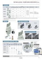
Soft Start-up Valve AV2000-A/3000-A/4000-A/5000-A Series Variations Q ∗1 C [l/min (ANR)] [dm3/(s·bar)] Electrical entry • Bracket • Pressure gauge • Silencer (Built-in) ∗1 These values have been calculated according to ISO 6358 and indicate the flow rate under standard conditions with an inlet pressure of 0.6 MPa (relative pressure) and a pressure drop of 0.1 MPa. ∗2 Only for the DC type. Pilot Valve Variations DIN terminal minal with connector nnector DIN terminal without connector ∗1 A DIN terminal conforming to EN-175301-803C (former DIN 43650C) Pressure gauge Manual Override Variations Silencer...
Open the catalog to page 3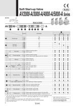
Body size *1 The 110 V AC and 115 V AC are interchangeable. The 220 V AC and 230 V AC are interchangeable as well. The allowable voltage fluctuation is -15 % to +5 % of the rated voltage for the 115 V AC or 230 V AC. *2 Only for the DC type. *3 Type “Y” is a DIN terminal conforming to EN-175301-803C (former DIN 43650C). *4 When the electrical entry is DO or YO, light/surge voltage suppressor cannot be selected. *5 Only for the NPT thread • Option: Select one each for a to c. • Option symbol: When more than one specification is required, indicate in alphabetical order. Example) AV2000-02BGS
Open the catalog to page 4
*1 These values have been calculated according to ISO 6358 and indicate the flow rate under standard conditions with an inlet pressure of 0.6 MPa (relative pressure) and a pressure drop of 0.1 MPa. Number of needle rotations
Open the catalog to page 5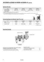
*1 Bracket: 1 pc., Mounting screw: 2 pcs. (3 pcs. for AV5000-A) *2 Element, Element O-ring, Element cover: 1 pc. for each *3 □ of the pressure gauge part number will indicate the connecting screw type. No indication is necessary for R; however, indicate N for NPT. Please contact SMC regarding the pressure gauge supply for psi unit specifications. Spacer with bracket *1 Except port size 06 Assembly Example © Spacer with bracket Products do not come assembled. They should be ordered separately and assembled by the customer. * The Simple Specials System deals with product unification. Please contact...
Open the catalog to page 6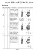
Working conditions Pilot valve Pressure conditions Operation description Internal construction/Cylinder actuation circuit (Meter-out control) example Operation description of the soft start-up valve When the pilot valve © is energised or turned ON manually, the spool © is pushed down due to the pilot air and gets into contact with the valve ©, closing the flow passage to port 3 (R). At this time, force that pushes the valve © > force that pushes down the spool ©. Therefore, the flow passage from the valve © to port 2 (A) is still closed. Furthermore, the piston © is pushed down due to the pilot...
Open the catalog to page 7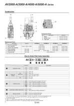
*1 See below for How to Order of the pilot valve. How to Order Pilot Valve Assembly *1 The 110 V AC and 115 V AC are interchangeable. The 220 V AC and 230 V AC are interchangeable as well. The allowable voltage fluctuation is -15 % to +5 % of the rated voltage for the 115 V AC or 230 V AC. *2 Only for the DC type. *3 Type “Y” is a DIN terminal conforming to EN-175301-803C (former DIN 43650C). *4 When the electrical entry is DO or YO, light/surge voltage suppressor cannot be selected. 7
Open the catalog to page 8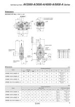
Soft Start-up Valve Dimensions Grommet: AV२00-२-२G२२-२-A AV5000-A Flow adjustment needle at low speed air supply Approx. 300 mm (Lead wire length) Manual override Pressure gauge port size 1/8 Pressure gauge (Option) Ø 37.5 Built-in silencer (Option) Bracket (Option) [mm] Standard specifications Port size Width across flats 22 Width across flats 24 Width across flats 30 Width across flats 36 [mm] Optional specifications With bracket With built-in silencer Width across flats 14 Width across flats 19 Width across flats 22
Open the catalog to page 9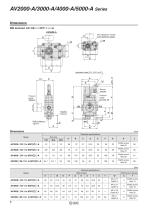
AV2000-A/3000-A/4000-A/5000-A Series Dimensions DIN terminal: AV२00-२-२D/Y२२-२-A AV5000-A Flow adjustment needle at low speed air supply Pressure gauge port size 1/8 Pressure gauge (Option) Bracket (Option) Built-in silencer (Option) Manual override [mm] Standard specifications Port size Width across flats 22 Width across flats 24 Width across flats 30 Width across flats 36 [mm] Optional specifications With bracket With built-in silencer Width across flats 14 Width across flats 19 Width across flats 2
Open the catalog to page 10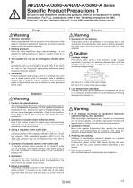
AV2000-A/3000-A/4000-A/5000-A Series Specific Product Precautions 1 Be sure to read this before handling the products. Refer to the back cover for safety instructions. For F.R.L. precautions, refer to the “Handling Precautions for SMC Products” and the “Operation Manual” on the SMC website: http://www.smc.eu 2. Holding pressure Since the valve might have slight internal leakage, it is not suitable for holding pressure in a tank or another vessel for a long period of time. 3. Not suitable for use as an emergency shutoff valve etc. The valves listed in this catalogue are not designed for safety...
Open the catalog to page 11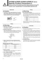
A V2000-A/3000-A/4000-A/5000-A Series Specific Product Precautions 2 Be sure to read this before handling the products. Refer to the back cover for safety instructions. For F.R.L. precautions, refer to the “Handling Precautions for SMC Products” and the “Operation Manual” on the SMC website: http://www.smc.eu 1. To perform the initial speed adjustment of the outlet side actuator, supply air from this valve’s inlet side and turn ON the pilot valve. Then, rotate the needle counterclockwise from the fully closed position. 1. Preparation before piping Before piping is connected, it should be thoroughly...
Open the catalog to page 12All SMC catalogs and technical brochures
 In-line Type Vacuum Ejector
6 Pages
 Serie HRR
64 Pages
 Série VP/VG
33 Pages
 Série XL
27 Pages
 Série ACG/ARG/AWG
45 Pages
 Série JXC5H/6H
36 Pages
 LEJS100-X400 series
15 Pages
 JMB series
13 Pages
 JCM series
21 Pages
 PF3A7*H
40 Pages
 PF3W
PF3W34 Pages
 Compact Guide Cylinder with Lock
36 Pages
 Water Treatment
16 Pages
 Food & Packaging Industry
4 Pages
 Digital Gap Checker
26 Pages
 Vacuum Pad
16 Pages
 One-touch Fittings
224 Pages
 Electric Actuator
272 Pages
 Rotary Actuator
40 Pages
 Compact Guide Cylinder
18 Pages
 Compact Slide
24 Pages
 Air Cylinder
124 Pages
 LEFB, LEFG-BS series
180 Pages
 JMGP series
16 Pages
 ISO Cylinder
32 Pages
 IZD10
IZD1020 Pages
 IZH10
IZH108 Pages
 Fan Type Lonizer
28 Pages
 Check Valves
4 Pages
 Compact Cylinder/Clean series
16 Pages
 3 port solenoid Valve
74 Pages
 Vacuum Ejector Series ZM
20 Pages
 Series ZL
20 Pages
 Series CM2
92 Pages
 Series IDGA/IDG
56 Pages
 Platform Cylinder Series CXT
14 Pages
 IDH-A
IDH-A12 Pages
 CP96-C96-B
74 Pages
 CVQ
CVQ24 Pages
 HY
HY52 Pages
 VNA
VNA10 Pages
 Series MXY
28 Pages
 Series MXP
39 Pages
 Air Slide Table
132 Pages
 Compact Cylinder Series CQ2
138 Pages
 S0700
S0700112 Pages
 SYJ
SYJ96 Pages
 SY - NEW
164 Pages
 VF
VF60 Pages
 C(D)55 series
24 Pages
 C(D)Q2 series
216 Pages
 MGP series
36 Pages
 11-LEFS series
19 Pages
 LECS series
16 Pages
 LECPA series
4 Pages
 KQ series
80 Pages
 IDF series
16 Pages
 ZP series
69 Pages
 MHF series
32 Pages
 MHZ series
68 Pages
 CRB series
44 Pages
 MGJ series
7 Pages
 AC series
98 Pages
 VH series
14 Pages
 LVA series
43 Pages
 VDW series
28 Pages
 LVM series
28 Pages
 VX2 series
32 Pages
 MXH series
32 Pages
 MXF series
12 Pages
 CXW series
48 Pages
 CXS series
76 Pages
 CQS series
40 Pages
 CQM series
28 Pages
 CLQ series
36 Pages


