- Products
- Catalogs
- News & Trends
- Exhibitions
Series MXY
1 /28Pages

Series MXY
1 /28Pages
Catalog excerpts
Air Slide Table Long Stroke A long-stroke type of Series MXP air slide table with integrated linear guide is newly released.
Open the catalog to page 1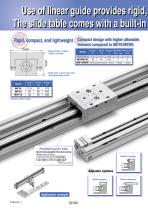
Use of linear guide provides rigid, The slide table comes with a built-in Compact design with higher allowable Rigid, compact, and lightweight Compact design with higher allowable moment compared to MXY8/MXW8 moment compared to MXY8/MXW8 Magnetically coupled rodless cylinder Width Weight Allowable moment N⋅m g mm Roll Pitch, Yaw 25 420 5.7 13 MXY8-50 47 MXW8-50 30 610 5 3 49 MXY/MXW 0.8 times 0.95 times 0.7 times 1.14 times 4 times Model Slide table is built with rigid and lightweight profile. Positioning pin hole Improved mounting repeatability of the work piece and body Rubber stopper Positioning...
Open the catalog to page 2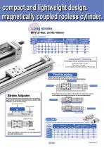
compact and lightweight design. magnetically coupled rodless cylinder. Long stroke MXY12-Max. stroke 400mm Series variations Bore size (mm) Adjuster options Rubber stopper Shock absorber Function options Metal stopper Piping concentrated on one side of the switch rail Auto switch mounting Three types of auto switches can be mounted. Solid state switch: F9 type Reed switch: A9 type 2-color display solid state switches: F9ǢW type Flexible piping 3 different piping directions are available: Horizontal piping, axial piping, and centralized piping Horizontal piping Axial piping Changing the mounting...
Open the catalog to page 3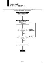
MXY Model Selection 1 Series The following are the steps for selection of the series MXY best suited to your application, Conditions and Calculation Flow for Selection Operating conditions m: Load mass (kg) Mounting Orientation: V : Speed (mm/s) Accuracy: P : Operating pressure (MPa) Tentative selection of cylinder model Bore size : ø6, ø8, ø12 Stopper: Metal Rubber Shock absorber Examine load mass and kinetic energy NG size UP Change of stopper Consideration of load factor [Σα]ͨ1 Examine auto switch mounting (Model) Model determination
Open the catalog to page 5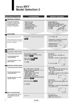
MXY Model Selection 2 Series Model Selection Procedure Selection Examples Operating conditions Enumerate the operating conditions considering the mounting position and work piece configuration. ⋅ Model to be used ⋅ Type of cushion ⋅ Mounting orientation ⋅ Average speed Va (mm/s) ⋅ Load weight W (kg) ⋅ Overhang Ln (mm) Cylinder: MXY8-100 Cushion: Rubber stopper Mounting: Horizontal wall mounting Average speed: Va = 300 [mm/s] Load weight: W = 0.2 [kg] W L2 = 40mm L3 = 50mm L2 Load weight Find the collision speed (mm/S) Confirm that the load mass W (kg) and collision speed do not exceed the value...
Open the catalog to page 6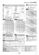
Model Selection Fig. 2 Allowable static load: F(N) Fig. 1 Overhang: Ln (mm), Corrected value of moment center position distance: An (mm) Pitch moment L1 Roll moment Dynamic moment Allowable static moment Ma N⋅m Table 2 Max. allowable load weight: Wmax (kg) Model Max. allowable load weight Table 4 Allowable static load: F(N) Pitch/Yaw moment: Mpmax/Mymax 5.7 The above value represents the applicable load at the position where the moment does not work at the time of stop. Factors such as impact, etc. are not in consideration with the value. Roll moment: Mrmax The above value represents the maximum...
Open the catalog to page 7
F9N S Number of auto switches Bore size-Standard stroke (mm) Auto switch type Shock absorber Metal stopper Without auto switch Rubber stopper One side centralized piping, switch rail One side centralized piping, without switch rail The auto switch cannot be mounted on the one side centralized piping type without switch rail (N). These auto switches have been changed Contact SMC or view www.smcworld.com One side centralized piping, with switch rail Solid state switch Reed switch Special function Electrical entry Indicator light Applicable auto switches/Refer to pages 11 through 15 for detailed...
Open the catalog to page 8
Model Bore size (mm) Port size Fluid Action Operating pressure Proof pressure Ambient and fluid temperature Piston speed Rubber bumper Shock absorber (option, not available on MXY6, MXY8) None (with metal stopper) Non-lube (equipment), unlubricated Standard Lubrication Stroke adjuster Rubber stopper Stroke adjustment Shock absorber range Metal stopper Reed switches (2-wire, 3-wire) Solid state switches (2-wire, 3-wire) 2-color display solid state switches (2-wire, 3-wire) +1 mm 0 Auto switch Stroke length tolerance Theoretical Output Cylinder bore (mm) Standard Stroke Model Magnetic Holding Force...
Open the catalog to page 9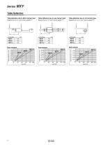
Table Deflection Table deflection due to pitch moment load Table deflection due to yaw moment load Table deflection due to roll moment load Displacement at "A" when load is applied "F" Displacement at "A" when load is applied "F" Displacement at "A" when load is applied "F" Roll moment Pitch moment
Open the catalog to page 10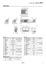
Metal stopper Shock absorber Parts list Material Heat treatment, electroless nickel plated Stopper screw Guide block Heat treatment, electroless nickel plated External magnet fix plate Aluminium alloy Hard anodized Cylinder scraper Aluminium alloy Hard anodized Lock plate Stainless steel Stainless steel Adjustment bolt Heat treatment Stainless steel NBR Stainless steel Steel Stainless steel Shock absorber 25 Electroless nickel plated Steel ball Nickel plated Rubber stopper Metal stopper Shock absorber Piston seal Electroless nickel plated Adjustment bumper Rare earth magnet Nickel plated Rare...
Open the catalog to page 11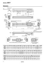
Dimensions Detail of part U TH (Head height of mounting bolt) Piping port Piping port 2-M5 x 0.8 (Plug: M-5P) Width across flats MB (lock plate fixing bolt) MA (Stroke adjuster) A (Stroke adjuster) HA Width across flats MB (lock plate fixing bolt) Piping port 2-M5 x 0.8 of the type centralized ( Same in case side withoutofswitch rail ) piping on one 2-M thread depth MM B D -Mounting reference planes Type of centralized piping on one side without switch rail Type of shock absorber (Only for MXY12) M5 x 0.8 (Width across flats 2.5) M6 x 1 (Width across flats 3) M8 x 1 (Width across flats 4) Model...
Open the catalog to page 12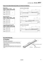
Proper Auto Switch Mounting Position for Stroke End Detection Reed switch Lead wire entries outside Lead wire entries inside Switch operating range 2-color display solid state switch Model Solid state switch Model Switch operating range Lead wire entries parallel Switch operating range Auto Switch Mounting Caution Auto switch mounting tools ț When tightening the auto switch set screw (included with auto switch), use a watchmakers screw driver with a handle diameter of about 5 to 6mm. Set screw (included with auto switch) Apply a torque of approximately 0.05 to 0.1N⋅m. As a rule, it can be tightened...
Open the catalog to page 13All SMC catalogs and technical brochures
 In-line Type Vacuum Ejector
6 Pages
 Serie HRR
64 Pages
 Série VP/VG
33 Pages
 Série XL
27 Pages
 Série ACG/ARG/AWG
45 Pages
 Série JXC5H/6H
36 Pages
 LEJS100-X400 series
15 Pages
 JMB series
13 Pages
 JCM series
21 Pages
 PF3A7*H
40 Pages
 PF3W
PF3W34 Pages
 Compact Guide Cylinder with Lock
36 Pages
 Water Treatment
16 Pages
 Food & Packaging Industry
4 Pages
 Digital Gap Checker
26 Pages
 Vacuum Pad
16 Pages
 One-touch Fittings
224 Pages
 Soft Start-up Valve
16 Pages
 Electric Actuator
272 Pages
 Rotary Actuator
40 Pages
 Compact Guide Cylinder
18 Pages
 Compact Slide
24 Pages
 Air Cylinder
124 Pages
 LEFB, LEFG-BS series
180 Pages
 JMGP series
16 Pages
 ISO Cylinder
32 Pages
 IZD10
IZD1020 Pages
 IZH10
IZH108 Pages
 Fan Type Lonizer
28 Pages
 Check Valves
4 Pages
 Compact Cylinder/Clean series
16 Pages
 3 port solenoid Valve
74 Pages
 Vacuum Ejector Series ZM
20 Pages
 Series ZL
20 Pages
 Series CM2
92 Pages
 Series IDGA/IDG
56 Pages
 Platform Cylinder Series CXT
14 Pages
 IDH-A
IDH-A12 Pages
 CP96-C96-B
74 Pages
 CVQ
CVQ24 Pages
 HY
HY52 Pages
 VNA
VNA10 Pages
 Series MXP
39 Pages
 Air Slide Table
132 Pages
 Compact Cylinder Series CQ2
138 Pages
 S0700
S0700112 Pages
 SYJ
SYJ96 Pages
 SY - NEW
164 Pages
 VF
VF60 Pages
 C(D)55 series
24 Pages
 C(D)Q2 series
216 Pages
 MGP series
36 Pages
 11-LEFS series
19 Pages
 LECS series
16 Pages
 LECPA series
4 Pages
 KQ series
80 Pages
 IDF series
16 Pages
 ZP series
69 Pages
 MHF series
32 Pages
 MHZ series
68 Pages
 CRB series
44 Pages
 MGJ series
7 Pages
 AC series
98 Pages
 VH series
14 Pages
 LVA series
43 Pages
 VDW series
28 Pages
 LVM series
28 Pages
 VX2 series
32 Pages
 MXH series
32 Pages
 MXF series
12 Pages
 CXW series
48 Pages
 CXS series
76 Pages
 CQS series
40 Pages
 CQM series
28 Pages
 CLQ series
36 Pages


