- Products
- Catalogs
- News & Trends
- Exhibitions
Platform Cylinder Series CXT
1 /14Pages

Platform Cylinder Series CXT
1 /14Pages
Catalog excerpts
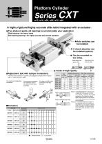
Platform Cylinder A highly rigid and highly accurate slide table integrated with an actuator. Two styles of guide rod bearings to accommodate your application Slide bearing—for heavy loads Ball bushing bearing—for highly accurate and smooth operation Auto switches can be installed. A shock absorber can be installed (option). Can be mounted on two sides. Mounting from upper side Mounting from bottom side Guide of high rigidity Adjustment bolt with bumper is standard. Performs the function of a cushion and adjusts the stroke 5mm on each side, or 10mm for both sides. For moving and transporting workpieces. For moving the receptacle for workpieces used in stamping or press-fitting processes. For using as a P&P unit in combination with other actuators. CXTM (Slide bearing) CXTL (Ball bushing bearing) Allowable Table static weight displacement (kg) (mm) Allowable static weight (kg) Note 1) "Table displacement" is the amount of deflection of the guide rod that occurs when a maximum load weight is placed on the maximum stroke table while the table is at the center of the stroke (the amount of looseness Note 2) Allowable static load is not included). Note 2) An "allowable stationary weight" is the allowable amount of stationary weight that can be applied vertically to the workpiece mounting surface of the table while the table is at the stroke end. Note 1) Table displacement Variations Bearing Slide Ball bushing ·····Standard stroke ·····Long stroke
Open the catalog to page 1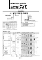
Platform Cylinder 100 B A90 S Number of auto switches Platform cylinder Ball bushing bearing Auto switch — Bore size/Stroke (mm) Bore size (mm) Slide bearing Without auto switch (Built-in magnet) Refer to p.2-118 for common specification and wire specification. ∗ Refer to the table below for part numbers for applicable auto switches. Adjusting bolt with bumper only (Standard) With 2 shock absorbers (Set only on the driving cylinder side when packed.) With 1 shock absorber (Set on the driving cylinder side when packed.) ·····Long stroke ∗ Refer to p.2-118 for minimum strokes for auto switch equipped...
Open the catalog to page 2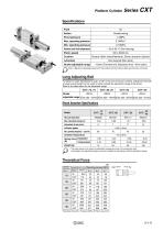
Platform Cylinder Specifications Fluid Double acting Proof pressure Ambient and fluid temperature Piston speed Bumper (Both sides/Standard), Shock absorber (Option) Stroke adjustable range –10mm (Forward end, Backward end: –5mm each) Note 1) Maximum operating pressure for this product with the bumper ability and the else concerned. Long Adjusting Bolt For Made to Order Specifications (add "-x138" to the end of the part number), adjustment bolt with a longer overall length can be used to further extend the adjustment range of the stroke. Refer to the table below for the adjustable range. –26mm...
Open the catalog to page 3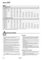
Weight CXTM (Slide bearing) Stroke (mm) CXTL (Ball bushing bearing) Stroke (mm) Note 1) Factors in parentheses are weight of movable parts (weight of movable parts of the cylinder is included.) Note 2) The weight indicated above does not include a shock absorber. Precautions for Handling Operation q Make sure not to apply to the slide block a load that exceeds the value that has been calculated in the selection procedure. w Operate the cylinder securing it by its plates, not by securing it by its slide block. e The clearance between the slide block and the plate at the stroke end is approximately...
Open the catalog to page 4
Selection Procedures Setting conditions 1. Mounting (Horizontal, Inclined, Vertical) 2. Movable weight W(kg) 3. Operating pressure P(MPa) P 0.7MPa 4. Speed V(mm/s) V 500mm/s Guideline for selection of bearing style Bearing Selection of bearing style Required conditions •Impact load and vibration load are added. •Change in load is large. •Long life span is required. Slide bearing •High accuracy (Little rattle is allowed.) Ball bushing bearing •Smooth operation Provisional selection of cylinder bore size Movable weight[W] Σαn= Max. movable weight[Wmax] + Allowable moment[Mn] NO Movable weight [W]...
Open the catalog to page 5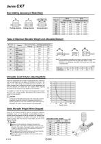
Non-rotating Accuracy of Slide Block θp (Slide bearing) (Ball bushing bearing) ±0.05° Yawing direction Rolling direction Pitching direction Table of Maximum Movable Weight and Allowable Moment Slide Ball bushing Slide Ball bushing Slide Ball bushing Slide Ball bushing Slide Ball bushing Slide Ball bushing Note) For the purpose of calculating the moment, the length of the arm is the distance that is measured from the guide shaft center (“•” mark). Dimension l from the guide shaft center to the top surface of the table is indicated below. Bore size Allowable Load Only by Adjusting Bolts In conditions...
Open the catalog to page 6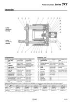
Platform Cylinder CXTM/ Guide rod, bearing CXTL/ Guide rod, bearing Component Parts Slide block Aluminum alloy Hard anodized Shock absorber Aluminum alloy Hard anodized Carbon steel Aluminum alloy Hard anodized Hex. socket head cap bolt Chrome molybdenum steel Nickel plated Aluminum alloy Hard anodized Aluminum alloy White anodized Slide bearing Aluminum alloy Ball bushing bearing Carbon tool steel Nickel plated Carbon steel Connected disk Carbon steel Flat seat metal CXTM Carbon steel Hard chrome plated CXTL Bearing steel High frequency quenching, Hard chrome plating Bearing alloy, Carbon steel...
Open the catalog to page 7
4-øLD Through, Counter bore øB Depth C Back side 4-J Depth JK Slide Ball bushing ∗ PA dimension is the center sorted factor of the L dimension. Long stroke Bore size (mm)
Open the catalog to page 8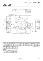
Platform Cylinder 4-ø8.7 Through, Counter bore ø14 Depth 8 Back side 4-M10 Depth 15 Slide Ball bushing ∗ PA dimension is the center sorted factor of the L dimension. Long stroke Bore (mm)
Open the catalog to page 9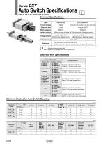
Auto Switch Specifications Refer to p.6-15 for details on auto switch. Common Specifications Style Reed switch Solid state switch Current leakage 3 wire style: 100 mA or less 2 wire style: 1mA or less Operating time Shock resistance Insulation resistance Voltage resistance 50MΩ or more at 500V DC (Electrical wire, Between bowls) 1 minute at 1500V AC(1) (Electrical wire, Between bowls) 1 minute at 1000V AC (Electrical wire, Between bowls) Ambient temperature IP67 according to IEC529 standard, C 0920 osmosis proof construction according to JIS standard Note 1) Electrical entry for the connector...
Open the catalog to page 10All SMC catalogs and technical brochures
 In-line Type Vacuum Ejector
6 Pages
 Serie HRR
64 Pages
 Série VP/VG
33 Pages
 Série XL
27 Pages
 Série ACG/ARG/AWG
45 Pages
 Série JXC5H/6H
36 Pages
 LEJS100-X400 series
15 Pages
 JMB series
13 Pages
 JCM series
21 Pages
 PF3A7*H
40 Pages
 PF3W
PF3W34 Pages
 Compact Guide Cylinder with Lock
36 Pages
 Water Treatment
16 Pages
 Food & Packaging Industry
4 Pages
 Digital Gap Checker
26 Pages
 Vacuum Pad
16 Pages
 One-touch Fittings
224 Pages
 Soft Start-up Valve
16 Pages
 Electric Actuator
272 Pages
 Rotary Actuator
40 Pages
 Compact Guide Cylinder
18 Pages
 Compact Slide
24 Pages
 Air Cylinder
124 Pages
 LEFB, LEFG-BS series
180 Pages
 JMGP series
16 Pages
 ISO Cylinder
32 Pages
 IZD10
IZD1020 Pages
 IZH10
IZH108 Pages
 Fan Type Lonizer
28 Pages
 Check Valves
4 Pages
 Compact Cylinder/Clean series
16 Pages
 3 port solenoid Valve
74 Pages
 Vacuum Ejector Series ZM
20 Pages
 Series ZL
20 Pages
 Series CM2
92 Pages
 Series IDGA/IDG
56 Pages
 IDH-A
IDH-A12 Pages
 CP96-C96-B
74 Pages
 CVQ
CVQ24 Pages
 HY
HY52 Pages
 VNA
VNA10 Pages
 Series MXY
28 Pages
 Series MXP
39 Pages
 Air Slide Table
132 Pages
 Compact Cylinder Series CQ2
138 Pages
 S0700
S0700112 Pages
 SYJ
SYJ96 Pages
 SY - NEW
164 Pages
 VF
VF60 Pages
 C(D)55 series
24 Pages
 C(D)Q2 series
216 Pages
 MGP series
36 Pages
 11-LEFS series
19 Pages
 LECS series
16 Pages
 LECPA series
4 Pages
 KQ series
80 Pages
 IDF series
16 Pages
 ZP series
69 Pages
 MHF series
32 Pages
 MHZ series
68 Pages
 CRB series
44 Pages
 MGJ series
7 Pages
 AC series
98 Pages
 VH series
14 Pages
 LVA series
43 Pages
 VDW series
28 Pages
 LVM series
28 Pages
 VX2 series
32 Pages
 MXH series
32 Pages
 MXF series
12 Pages
 CXW series
48 Pages
 CXS series
76 Pages
 CQS series
40 Pages
 CQM series
28 Pages
 CLQ series
36 Pages


