- Products
- Catalogs
- News & Trends
- Exhibitions
MXF series

MXF series
Mounting Options: Offers flexibility with body tapped and through-hole mounting options, specifying bolt sizes and torque requirements for each model.
Mounting of Work Piece: Workpieces can be mounted on two sides, with specified bolt sizes, torque, and screw-in depths.
Precautions: Avoid damage to mounting surfaces, keep away from magnetic fields, use appropriate screws, and ensure flatness of 0.02mm or less.
Component Parts and Materials: Lists materials and treatments for components like the body, table, and seals.
Replacement Parts: Seal kits available for different bore sizes, including piston seals, rod seals, and O-rings.
Dimensions: Provides detailed dimensions for models MXF8, MXF12, MXF16, and MXF20.
Auto Switch Specifications: Details compatible auto switch models, mounting positions, and operation ranges.
Catalog excerpts
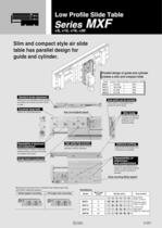
Low Profile Slide Table Series ø8, ø12, ø16, ø20 MXF Slim and compact style air slide table has parallel design for guide and cylinder. Parallel design of guide and cylinder creates a slim and compact slide. Model Height x Width(mm) Height comparison to MXS MXF8 16 X 58 67% MXF12 18.5 X 68 59% MXF16 21 X 80 53% MXF20 27 X 92 54% Standard stroke adjustment Auto switch can be mounted Stroke can be adjusted at each stroke end within 5mm each end and 10mm in total. Auto switch is recessed in the groove to save space. Covered stop bolt Allows for neat appearance. Body mounting(Body tapped) Slim body Parallel arrangement of guide and cylinder achieves a thin cylinder profile. Repeatability of attachment and unattachment Positioning pin holes on table top allows precise and easy mounting to change work piece. High rigidity/High precision Optional porting Cross roller guide allows smooth operation without vibration. Lateral and axial piping from 2 directions is possible. Repeatability of attachment and unattachment Stronger thread for mounting work Helisert thread for mounting work Pin holes for positioning on bottom of slide allows precise and accurate mounting of actuator. Body mounting (Body tapped) Mounting can be done from 2 directions top side(through hole) and bottom side(body tapped). qBody tapped mounting wThrough hole mounting Variations Bore size (mm) MXF8 8 MXF12 12 MXF16 16 MXF20 20 Stroke (mm) Auto switch 10 20 30 50 75 100 Model Reed switch D-A9, D-A9V Solid state switch D-M9, D-M9V 2 colour solid state switch D-M9W, D-M9WV 2-221
Open the catalog to page 1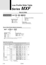
Low Profile Slide Table Low Profile Slide Table Number of auto switches Auto switch Without auto switch Select the auto switch from the list below. How to Order Stroke Adjuster (Accessory) Applicable cylinder bore size Adjustable range J\ * -X12 (Adjustable range 25mm) is not available for series MXF8/MXF12. * -X11 and -X12 are not available as built-in product. Applicable Auto Switches * Lead wire length
Open the catalog to page 2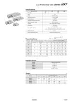
Low Profile Slide Table Series MXF Theoretical Force Note) Theoretical force (N)=Pressure (MPa) X Piston area(mm2) Standard Stroke
Open the catalog to page 3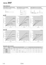
Table Deflection Table deflection by pitch moment Table deflection by yaw moment Table deflection by roll moment Table pitch deflection due to static pitch moment applied Table yaw deflection due to static yaw moment applied at arrow for all strokes of slide table. at arrow for all strokes of slide table. Table roll deflection arrow A due to static roll moment applied at arrow F when Lr=20mm and table is retracted. Allowable static moment
Open the catalog to page 4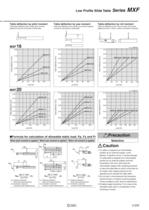
MXF Series Low Profile Slide Table Table deflection by pitch moment Table deflection by yaw moment Table deflection by roll moment Table pitch deflection due to static pitch moment applied at arrow for all strokes of slide table. Table yaw deflection due to static yaw moment applied at arrow for all strokes of slide table. Table roll deflection arrow A due to static roll moment applied at arrow F when Lr=20mm and table is retracted. F A A Lr MXF 16 Lr=40mm 0.06 Table deflection (mm) Table deflection (mm) MXF16-75 0.16 0.12 MXF16-50 0.08 MXF16-30 0.04 0.07 0.06 MXF16-75 0.05 0.04 MXF16-50 0.03...
Open the catalog to page 5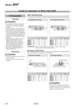
Guide for Operation of Slide Table MXF ©Do not scratch or dent the mounting side of the body, table or end plate. It causes play in the guide section and increases sliding ©Do not apply scratch or dent the forward side of the rail or guide. It can cause play of the guide section and increases sliding resistance. ©Do not bring into close contact with objects which would be influenced by a magnetic field. As an air slide table has magnets built-in, do not allow close contact with magnetic disks, magnetic cards or magnetic tapes. Data may ©When mounting an air slide table, screws of appropriate...
Open the catalog to page 6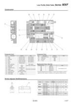
Low Profile Slide Table Series MXF Component Parts Component Parts Replacement Parts: Seal Kits * The parts Indicated with the numbers ©, © and © are included in a seal kit. Specify the order numbers in compliance with respective cylinder bore size. Stroke Adjuster Bolt/Dimensions
Open the catalog to page 7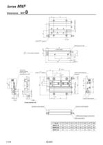
Retraction stroke adjuster Extension stroke adjuster
Open the catalog to page 8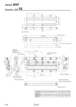
(Table length) Blank plug Retraction stroke adjuster Extension stroke adjuster Width across hexagon socket hole 3 Width across flats f
Open the catalog to page 10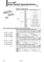
Auto Switch Specifications * Refer to p.6-15 for the detailed specifications on auto switches Applicable Auto Switch Model Bore size Auto switch model Reed switch Solid state Electrical entry/Function 3 wire(NPN), 2 colour, In-line 3 wire(PNP), 2 colour, In-line 2 wire, 2 colour, In-line 3 wire(NPN), 2 colour, Perpendicular 3 wire(PNP), 2 colour, Perpendicular 2 wire, 2 colour, Perpendicular Auto Switch/Suitable Mounting Position for End of Stroke Detection
Open the catalog to page 12All SMC catalogs and technical brochures
 In-line Type Vacuum Ejector
6 Pages
 Serie HRR
64 Pages
 Série VP/VG
33 Pages
 Série XL
27 Pages
 Série ACG/ARG/AWG
45 Pages
 Série JXC5H/6H
36 Pages
 LEJS100-X400 series
15 Pages
 JMB series
13 Pages
 JCM series
21 Pages
 PF3A7*H
40 Pages
 PF3W
PF3W34 Pages
 Compact Guide Cylinder with Lock
36 Pages
 Water Treatment
16 Pages
 Food & Packaging Industry
4 Pages
 Digital Gap Checker
26 Pages
 Vacuum Pad
16 Pages
 One-touch Fittings
224 Pages
 Soft Start-up Valve
16 Pages
 Electric Actuator
272 Pages
 Rotary Actuator
40 Pages
 Compact Guide Cylinder
18 Pages
 Compact Slide
24 Pages
 Air Cylinder
124 Pages
 LEFB, LEFG-BS series
180 Pages
 JMGP series
16 Pages
 ISO Cylinder
32 Pages
 IZD10
IZD1020 Pages
 IZH10
IZH108 Pages
 Fan Type Lonizer
28 Pages
 Check Valves
4 Pages
 Compact Cylinder/Clean series
16 Pages
 3 port solenoid Valve
74 Pages
 Vacuum Ejector Series ZM
20 Pages
 Series ZL
20 Pages
 Series CM2
92 Pages
 Series IDGA/IDG
56 Pages
 Platform Cylinder Series CXT
14 Pages
 IDH-A
IDH-A12 Pages
 CP96-C96-B
74 Pages
 CVQ
CVQ24 Pages
 HY
HY52 Pages
 VNA
VNA10 Pages
 Series MXY
28 Pages
 Series MXP
39 Pages
 Air Slide Table
132 Pages
 Compact Cylinder Series CQ2
138 Pages
 S0700
S0700112 Pages
 SYJ
SYJ96 Pages
 SY - NEW
164 Pages
 VF
VF60 Pages
 C(D)55 series
24 Pages
 C(D)Q2 series
216 Pages
 MGP series
36 Pages
 11-LEFS series
19 Pages
 LECS series
16 Pages
 LECPA series
4 Pages
 KQ series
80 Pages
 IDF series
16 Pages
 ZP series
69 Pages
 MHF series
32 Pages
 MHZ series
68 Pages
 CRB series
44 Pages
 MGJ series
7 Pages
 AC series
98 Pages
 VH series
14 Pages
 LVA series
43 Pages
 VDW series
28 Pages
 LVM series
28 Pages
 VX2 series
32 Pages
 MXH series
32 Pages
 CXW series
48 Pages
 CXS series
76 Pages
 CQS series
40 Pages
 CQM series
28 Pages
 CLQ series
36 Pages


