- Products
- Catalogs
- News & Trends
- Exhibitions
MK

MK
Catalog excerpts

Rotary Clamp Cylinder Allowable moment of inertia 3 times higher New structure! MK series is released!! Overall length is the same as the existing products! Mounting dimensions are interchangeable with the MK series. Possible to mount small auto switches on 4 surfaces • Auto switches can be mounted on any of the 4 surfaces to suit the installation conditions (2 surfaces for o20 and o25). • No projection of auto switch Rotary stroke 2-color indication solid state auto switch Accurate setting of the mounting position can be performed without mistakes A *TEpt light indicates the proper ^^^^^^ operating range. operating range Application Example Clamp stroke
Open the catalog to page 1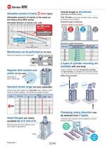
Allowable moment of inertia 3 times higher Allowable moment of inertia is the same as Allowable Moment of Inertia (032, 040) (Heavy-duty type) Piston speed [trim's] Maintenance can be performed for all sizes. Seal kit and guide pin are replaceable. Magnetic field resistant auto ^ Standard stroke range has been expanded. Strokes have been added to the New MK series, making a wide range of strokes available. ("^ indicates the added strokes.) Head flanges are newly Mounting type has been added to suit a wide range of applications. Overall length is shortened. 3 tO 10 mm shorter than the MK2 series,...
Open the catalog to page 2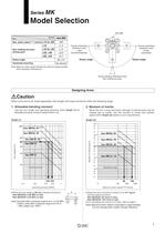
Model Selection Max. piston speed Note) [mm/s] o12 to o63 Non-rotating accuracy (Clamp part) Rotary angle Horizontal mounting Note) Maximum piston speed indicates the maximum speed possible when employing a standard arm. During unclamping Rotary angle Port side During unclamping Rotary angle During clamping (Retraction end) Non-rotating accuracy Designing Arms When arms are to be made separately, their length and mass should be within the following range. 1. Allowable bending moment Use the arm length and operating pressure within Graph (1) for allowable bending moment loaded piston rod. Operating...
Open the catalog to page 3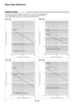
Bore Size Selection Note) Maximum piston speed is equivalent to approximately 1.6x the average piston speed. (Rough Indication) Calculate the operating conditions and operate this product within the allowable range. If the allowable range is exceeded, increase the bore size or use the MK2T series. (Refer to SMC Best Pneumatics No. 3 for details of the MK2T series.) Maximum piston speed [mm/s] Maximum piston speed [mm/s] Maximum piston speed [mm/s] Maximum piston speed [mm/s]
Open the catalog to page 4
Bore Size Selection Note) Maximum piston speed is equivalent to approximately 1.6x the average piston speed. (Rough Indication) Calculation example when arms other than the options are used. • Calculate the moment of inertia of the clamping jig • Calculate the moment of inertia of the arm. ■(Calculation example> when the cylinder bore Size ÍS 032. Clamping jig: h • Calculate the actual moment of inertia. Calculation result (when the bore size is o32 and clamp stroke is 10 mm.) Note 1) Average piston speed = Max. piston speed -M .6 Note 2) Total stroke = Clamp stroke + Rotary stroke Note 3) Total...
Open the catalog to page 5
Bore Size Selection Do not use the cylinder under the following environments: • An area in which fluids such as cutting oil splash on the piston rod • An area in which foreign matter such as particles, cutting chips, or dust is present • An area in which the ambient temperature exceeds the operating range • An area exposed to direct sunlight • An environment that poses the risk of corrosion A cylinder could malfunction or the non-rotating accuracy could be affected if a rotational force is applied to the piston rod. Therefore, observe the particulars given below before operating the cy- 1) Make...
Open the catalog to page 6
Rotary Clamp Cylinder: Standard Rotary clamp cylinder Mounting bracket ■ Head flanges are shipped together, (but Bore size* Port thread type Clamp stroke (Refer to the next page Auto switch type •Auto switch type Auto switch multiple side mounting Without auto switch (Built-in magnet) Body option ■ For applicable auto switch models. refer to the below table. ■ Auto switches are shipped * Arms are shipped together, (but not Rotary direction (Unclamp -» Clamp) During unclamping During unclamping During clamping (Retraction end) Applicable Auto Switches/Refer to Best Pneumatics No. 3 for further...
Open the catalog to page 7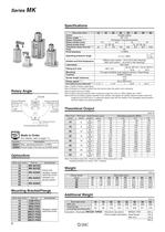
Rotary Angle During unclamping During unclamping Clamp part / \ Non-rotating accuracy During clamping (Retraction end) (Fordetails, referto page 17.] Mounting Bracket/Flange Note 1 ) Refer to Rotary Angle figure. Note 2) Direction of rotation viewed from the rod end when the piston rod is retracting Note 3) Clamp force at 0.5 MPa Note 4) When using the cylinder within a pressure range from 0.61 to 1 MPa, please use -X2071. Note 5) Be sure to install a speed controller to the cylinder, and adjust the cylinder speed to make it within the range from 50 to 200 mm/s. To adjust the speed, start with...
Open the catalog to page 8
Rotary Clamp Cylinder: Standard Series MK Mounting Bolt for MKB-Z Mounting: Mounting bolt for through-hole type is available. Refer to the following for ordering procedures. Order the actual number of bolts that will be used. Mounting boll Flat washer/ Note) Be sure to use a flat washer to mount cylinders via through-holes. Use a clamp arm that is available as an option. To fabricate a clamp arm, make sure that the allowable bending moment and the inertial moment will be within the specified range. Refer to Graph 1 and 2 on page 1. Ensuring Safety If one side of the piston is pressurized by supplying...
Open the catalog to page 9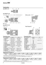
Component Parts Component Parts * Seal kit includes numbers in the table. Order the seal kit, based on each bore size. * Since the seal kit does not include a grease pack, order it separately. Grease pack part no.: GR-S-010 (10 g) Guide pin kit includes numbers in the table. Order the guide pin kit, based on each bore size. For the replacement procedure of the replacement parts/seal and guide pin kits, refer to the Operation Manual.
Open the catalog to page 10
Rotary Clamp Cylinder: Standard Series MK The outline dimensions shown are when the rod is retracted. Through-hole/Both ends tapped common E effective thread depth F Auto switch Minimum bending radius Note) The above figure is with the auto switch (D-M9D) mounted. Rotary direction: L ^orl side Rotary direction: R During unclamping During unclamping During clamping Head flange Head Flange
Open the catalog to page 11All SMC catalogs and technical brochures
 In-line Type Vacuum Ejector
6 Pages
 Serie HRR
64 Pages
 Série VP/VG
33 Pages
 Série XL
27 Pages
 Série ACG/ARG/AWG
45 Pages
 Série JXC5H/6H
36 Pages
 LEJS100-X400 series
15 Pages
 JMB series
13 Pages
 JCM series
21 Pages
 PF3A7*H
40 Pages
 PF3W
PF3W34 Pages
 Compact Guide Cylinder with Lock
36 Pages
 Water Treatment
16 Pages
 Food & Packaging Industry
4 Pages
 Digital Gap Checker
26 Pages
 Vacuum Pad
16 Pages
 One-touch Fittings
224 Pages
 Soft Start-up Valve
16 Pages
 Electric Actuator
272 Pages
 Rotary Actuator
40 Pages
 Compact Guide Cylinder
18 Pages
 Compact Slide
24 Pages
 Air Cylinder
124 Pages
 LEFB, LEFG-BS series
180 Pages
 JMGP series
16 Pages
 ISO Cylinder
32 Pages
 IZD10
IZD1020 Pages
 IZH10
IZH108 Pages
 Fan Type Lonizer
28 Pages
 Check Valves
4 Pages
 Compact Cylinder/Clean series
16 Pages
 3 port solenoid Valve
74 Pages
 Vacuum Ejector Series ZM
20 Pages
 Series ZL
20 Pages
 Series CM2
92 Pages
 Series IDGA/IDG
56 Pages
 Platform Cylinder Series CXT
14 Pages
 IDH-A
IDH-A12 Pages
 CP96-C96-B
74 Pages
 CVQ
CVQ24 Pages
 HY
HY52 Pages
 VNA
VNA10 Pages
 Series MXY
28 Pages
 Series MXP
39 Pages
 Air Slide Table
132 Pages
 Compact Cylinder Series CQ2
138 Pages
 S0700
S0700112 Pages
 SYJ
SYJ96 Pages
 SY - NEW
164 Pages
 VF
VF60 Pages
 C(D)55 series
24 Pages
 C(D)Q2 series
216 Pages
 MGP series
36 Pages
 11-LEFS series
19 Pages
 LECS series
16 Pages
 LECPA series
4 Pages
 KQ series
80 Pages
 IDF series
16 Pages
 ZP series
69 Pages
 MHF series
32 Pages
 MHZ series
68 Pages
 CRB series
44 Pages
 MGJ series
7 Pages
 AC series
98 Pages
 VH series
14 Pages
 LVA series
43 Pages
 VDW series
28 Pages
 LVM series
28 Pages
 VX2 series
32 Pages
 MXH series
32 Pages
 MXF series
12 Pages
 CXW series
48 Pages
 CXS series
76 Pages
 CQS series
40 Pages
 CQM series
28 Pages
 CLQ series
36 Pages


