- Products
- Catalogs
- News & Trends
- Exhibitions
LECS series
1 /16Pages

LECS series
1 /16Pages
Catalog excerpts
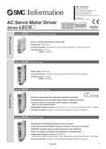
AC Servo Motor Driver Series LECS- Power Supply Voltage ©2012 SMC Corporation All Rights Reserved Motor Capacity Series LECSA (Pulse Input Type/Positioning Type) Up to 7 positioning points by point table 1 Input type: Pulse input 'Control encoder: Incremental 17-bit encoder (Resolution: 131072 pulse/rev) 1 Parallel input: 6 inputs Series LECSB (Pulse Input Type) • Input type: Pulse input • Control encoder: Absolute 18-bit encoder (Resolution: 262144 pulse/rev) • Parallel input: 10 inputs Series LECSC (CC-Link Direct Input Type) • Position data/speed data setting and operation start/stop • Positioning by up to 255 point tables (when 2 stations occupied) • Up to 32 drivers connectable (when 2 stations occupied) with CC-Link communication • Applicable Fieldbus protocol: CC-Link (Ver. 1.10, max. communication speed: 10 Mbps) • Control encoder: Absolute 18-bit encoder (Resolution: 262144 pulse/rev) Series LECSS (SSCNET III Type) > Compatible with Mitsubishi Electric's servo system > Reduced wiring and SSCNET III optical cable for one-touch connection > SSCNET III optical cable provides enhanced noise resistance 1 Up to 16 drivers connectable with SSCNET III communication ' Applicable Fieldbus protocol: SSCNET III (High-speed optical communication, max. bidirectional communication speed: 100 Mbps) > Control encoder: Absolute 18-bit encoder (Resolution: 262144 pulse/rev)
Open the catalog to page 1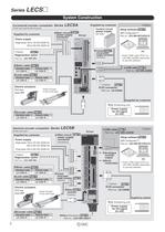
Series LECS२ System Construction Incremental encoder compatible Series LECSA Supplied by customer (Pulse input type/Positioning type) Control circuit power supply 24 VDC Main circuit Page 9 power supply Driver connector Supplied by customer Power supply Option Setup software Page 16 (MR ConfiguratorTM) Part no.: LEC-MR-SETUP221E (Accessory) Single phase 100 to 120 VAC (50/60 Hz) 200 to 230 VAC (50/60 Hz) Option Control Page 9 circuit power supply connector Page 15 Regeneration option Order USB cable (Part no.: LEC-MR-J3USB) separately to use this software. (Accessory) Part no.: LEC-MR-RB-२ Motor...
Open the catalog to page 2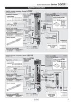
System Construction Series LECS २ System Construction LECSC Absolute encoder compatible Series (CC-Link direct input type) Supplied by customer Power supply Single phase 100 to 120 VAC (50/60 Hz) 200 to 230 VAC (50/60 Hz) Driver Main circuit Page 10 power supply connector (Accessory) Setup software Page 16 (MR ConfiguratorTM) Part no.: LEC-MR-SETUP221E Three phase 200 to 230 VAC (50/60 Hz) Option Option USB cable Page 16 Part no.: LEC-MR-J3USB Page 15 RS-422 communication Regeneration option Part no.: LEC-MR-RB-२ PC Page 15 Motor cable Standard cable Robotic cable LE-CSM-S२२ LE-CSM-R२२ Lock cable...
Open the catalog to page 3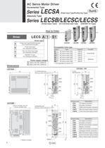
AC Servo Motor Driver Incremental Type Series LECSA (Pulse Input Type/Positioning Type) Absolute Type Series LECSB/LECSC/LECSS (Pulse Input Type) (CC-Link Direct Input Type) (SSCNET III Type) Power supply voltage Compatible motor type (Bearing surface thickness 4)
Open the catalog to page 4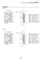
AC Servo Motor Driver Series LECS\J (Bearing surface thickness 4)\ * Battery included. (Bearing surface thickness 4)\ * Battery included.
Open the catalog to page 5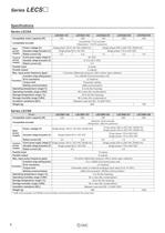
Series LECSD Series LECSA Series LECSB *1 USB communication and RS422 communication cannot be performed at the same time.
Open the catalog to page 6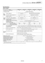
AC Servo Motor Driver Series LECS\J Series LECSC *1 If the system comprises of both CC-Link Ver. 1.00 and Ver. 1.10 compliant cables, Ver. 1.00 specifications are applied to the cable extensions and the cable length between stations. *2 USB communication and RS-422 communication cannot be performed at the same time.
Open the catalog to page 7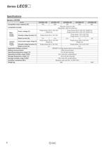
Series LECSD Series LECSS
Open the catalog to page 8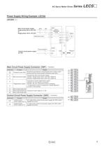
AC Servo Motor Driver Series LECS\J Power Supply Wiring Example: LECSA Main circuit power supply Regeneration option Control circuit power supply Circuit protector Main Circuit Power Supply Connector: CNP1 * Accessory Control Circuit Power Supply Connector: CNP2
Open the catalog to page 9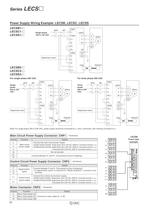
Series LECS\J Power Supply Wiring Example: LECSB, LECSC, LECSS Single phase Note) For single phase 200 to 230 VAC, power supply should be connected to Li and l_2 terminals, with nothing connected to l_3. Main Circuit Power Supply Connector: CNP1 * Accessory Control Circuit Power Supply Connector: CNP2 * Accessory Motor Connector: CNP3 * Accessory Front view
Open the catalog to page 10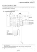
AC Servo Motor Driver Series LECS\J Control Signal Wiring Example: LECSA This wiring example shows connection with a PLC (FX3U-CDMT/ES) manufactured by Mitsubishi Electric as when used in position control mode. Refer to the LECSA operation manual and any technical literature or operation manuals for your PLC and positioning unit before connecting to another PLC or positioning unit. FX3U-DDMT/ES (Manufactured by Mitsubishi Electric) Forced stop Forward rotation stroke end Reverse rotation stroke end brake interlock A-phase pulse detector (Differential line driver) B-phase pulse detector (Differential...
Open the catalog to page 11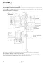
Series LECSD Control Signal Wiring Example: LECSB This wiring example shows connection with a positioning unit (QD75D) manufactured by Mitsubishi Electric as when used in position control mode. Refer to the LECSB operation manual and any technical literature or operation manuals for your PLC and positioning unit before connecting to another PLC or positioning unit. Positioning unit Mitsubishi Electric) Emergency stop Proportion control External torque limit selection Forward rotation stroke end Reverse rotation stroke end Upper limit setting Ft <^ Analogue torque limit Zero speed detection Torque...
Open the catalog to page 12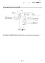
AC Servo Motor Driver Series LECS\J Control Signal Wiring Example: LECSC Forced stop Forward rotation stroke end Reverse rotation stroke end Home position return completion Z-phase pulse detector (Differential line driver) A-phase pulse detector (Differential line driver) B-phase pulse detector (Differential line driver) Control common Note 1) For preventing electric shock, be sure to connect the driver's protective earth (PE) terminal (markedo) to the control panel's protective earth (PE). Note 2) For interface use, supply 24 VDC ±10% 150 mA using an external source. Note 3) The failure (ALM)...
Open the catalog to page 13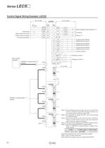
Series LECSD Control Signal Wiring Example: LECSS Forced stop Upper stroke limit (FLS) Lower stroke limit (RLS) Servo system A-phase pulse detector (Differential line driver) B-phase pulse detector (Differential line driver) Z-phase pulse detector (Differential line driver) Control common Note 1) For preventing electric shock, be sure to connect the driver's protective earth (PE) terminal (marked o) to the control panel's protective earth (PE). Note 2) For interface use, supply 24 VDC ±10% 150 mA using Note 3) The failure (ALM) is ON during normal conditions. When it is OFF (alarm occurs), stop...
Open the catalog to page 14All SMC catalogs and technical brochures
 In-line Type Vacuum Ejector
6 Pages
 Serie HRR
64 Pages
 Série VP/VG
33 Pages
 Série XL
27 Pages
 Série ACG/ARG/AWG
45 Pages
 Série JXC5H/6H
36 Pages
 LEJS100-X400 series
15 Pages
 JMB series
13 Pages
 JCM series
21 Pages
 PF3A7*H
40 Pages
 PF3W
PF3W34 Pages
 Compact Guide Cylinder with Lock
36 Pages
 Water Treatment
16 Pages
 Food & Packaging Industry
4 Pages
 Digital Gap Checker
26 Pages
 Vacuum Pad
16 Pages
 One-touch Fittings
224 Pages
 Soft Start-up Valve
16 Pages
 Electric Actuator
272 Pages
 Rotary Actuator
40 Pages
 Compact Guide Cylinder
18 Pages
 Compact Slide
24 Pages
 Air Cylinder
124 Pages
 LEFB, LEFG-BS series
180 Pages
 JMGP series
16 Pages
 ISO Cylinder
32 Pages
 IZD10
IZD1020 Pages
 IZH10
IZH108 Pages
 Fan Type Lonizer
28 Pages
 Check Valves
4 Pages
 Compact Cylinder/Clean series
16 Pages
 3 port solenoid Valve
74 Pages
 Vacuum Ejector Series ZM
20 Pages
 Series ZL
20 Pages
 Series CM2
92 Pages
 Series IDGA/IDG
56 Pages
 Platform Cylinder Series CXT
14 Pages
 IDH-A
IDH-A12 Pages
 CP96-C96-B
74 Pages
 CVQ
CVQ24 Pages
 HY
HY52 Pages
 VNA
VNA10 Pages
 Series MXY
28 Pages
 Series MXP
39 Pages
 Air Slide Table
132 Pages
 Compact Cylinder Series CQ2
138 Pages
 S0700
S0700112 Pages
 SYJ
SYJ96 Pages
 SY - NEW
164 Pages
 VF
VF60 Pages
 C(D)55 series
24 Pages
 C(D)Q2 series
216 Pages
 MGP series
36 Pages
 11-LEFS series
19 Pages
 LECPA series
4 Pages
 KQ series
80 Pages
 IDF series
16 Pages
 ZP series
69 Pages
 MHF series
32 Pages
 MHZ series
68 Pages
 CRB series
44 Pages
 MGJ series
7 Pages
 AC series
98 Pages
 VH series
14 Pages
 LVA series
43 Pages
 VDW series
28 Pages
 LVM series
28 Pages
 VX2 series
32 Pages
 MXH series
32 Pages
 MXF series
12 Pages
 CXW series
48 Pages
 CXS series
76 Pages
 CQS series
40 Pages
 CQM series
28 Pages
 CLQ series
36 Pages


