- Products
- Catalogs
- News & Trends
- Exhibitions
JMGP series
1 /16Pages

JMGP series
1 /16Pages
Catalog excerpts
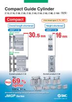
Compact Guide Cylinder Ø 12, Ø 16, Ø 20, Ø 25, Ø 32, Ø 40, Ø 50, Ø 63, Ø 80, Ø 100 ¡Port thread types G, Rc, NPT. Overall length shortened Height shortened 69 % lighter 0.32 kga0.1 kg (Compared with the current MGP-Z series, Ø 16, 10 mm stroke) for pushing, lifting or clamping in a transport line.
Open the catalog to page 1
Compact Guide Cylinder JMGP Series Compact Height (Compared with the current product (MGP-Z)) Overall length (Compared with the current product (MGP-Z)) Bore size - Stroke [mm] *1: Bore size 10 *2: Bore size 15 *1: Bore size 10 *2: Bore size 15 Internal structure Auto switch mounting groove Height Magnet (for auto switch) Collar (Bearing) Piston rod • Suitable for pushing, lifting or clamping in a transport line. Piping is possible in 4 directions
Open the catalog to page 2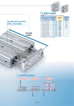
The solid state auto switch D-M9D is mountable. Overall length Bore size - Stroke [mm]
Open the catalog to page 3
* For details about auto switches with pre-wired connector, refer to the Auto Switch Guide. * Auto switches are shipp
Open the catalog to page 4
Compact Guide Cylinder JMGP Series • Auto switch proper mounting position (detection at stroke end) and mounting height • Minimum stroke for auto switch mounting • Operating range
Open the catalog to page 5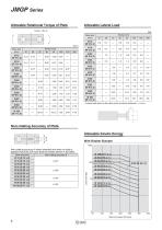
Allowable Lateral Load
Open the catalog to page 6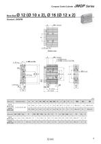
JMGP Series Compact Guide Cylinder Bore Size Bottom view WA + Stroke/2 4 x Ø OA through 4 x Ø OB counterbore depth OL Standard stroke Bore size
Open the catalog to page 7
JMGP Series Bore size
Open the catalog to page 8
Compact Guide Cylinder Bore Size JMGP Series Bottom view 2 x P (Plug) WA + Stroke/2 4 x Ø OA through 4 x Ø OB counterbore depth OL Standard stroke Bore size
Open the catalog to page 9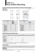
IJMGP Series Auto Switch Proper Auto Switch Mounting Height[mm] Auto switch model Bore size Note) Adjust the auto switch after confirming the operating condition in the actual setting. * Values which include hysteresis are for guideline purposes only, they are not a guarantee (assuming approximately ±30 % dispersion) and may change substantially depending on the ambient environment.
Open the catalog to page 11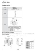
Auto Switch Mounting Applicable auto switches Bore size Surfaces with auto switch mounting slot Auto switch mounting surfaces Mounting of auto switch ♦ When tightening the auto switch mounting screw, use a watchmakers' screwdriver with a handle 5 to 6 mm in diameter. Tightening Torque for Auto Switch Mounting Screw [N-m] Caution on Proximity Installation When cylinders are adjacent to one another as shown in the figure below, provide a space between them of at least, the amount shown in the tables below. If the space is not sufficient, the magnets in adjacent cylinders may cause the auto switches...
Open the catalog to page 12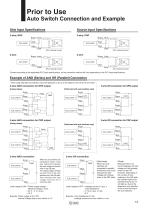
Prior to Use Auto Switch Connection and Example Sink Input Specifications Source Input Specifications Auto switch Brown Input Auto switch Brown Input Auto switch Brown COM Auto switch Blue Connect according to the applicable PLC input specifications, as the connection method will vary depending on the PLC input specifications. Example of AND (Series) and OR (Parallel) Connection ∗ When using solid state auto switches, ensure the application is set up so the signals for the first 50 ms are invalid. 3-wire AND connection for NPN output (Using relays) Brown Auto switch 1 3-wire OR connection for NPN...
Open the catalog to page 13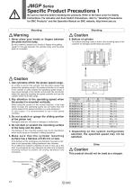
JMGP Series Specific Product Precautions 1 Be sure to read this before handling the products. Refer to the back cover for Safety Instructions. For Actuator and Auto Switch Precautions, refer to “Handling Precautions for SMC Products” and the Operation Manual on SMC website, http://www.smc.eu 1. Never place your hands or fingers between the plate and the body. Be very careful to prevent your hands or fingers from getting caught in the gap between the cylinder body and the plate when air is applied. A Caution 1. Use cylinders within the piston speed range. An orifice is set for this cylinder, but...
Open the catalog to page 14
JMGP Series Specific Product Precautions 2 Be sure to read this before handling the products. Refer to the back cover for Safety Instructions. For Actuator and Auto Switch Precautions, refer to “Handling Precautions for SMC Products” and the Operation Manual on SMC website, http://www.smc.eu |Piping ACaution Depending on the operating conditions, piping port positions can be changed by using a plug. When switching the plugged port, check for the air leakage. If small air leakage is detected, order the below plugs, and reassemble it. Plug Part Number G port Screw in the plug to the surface of...
Open the catalog to page 15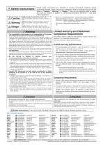
These safety instructions are intended to prevent hazardous situations and/or equipment damage. These instructions indicate the level of potential hazard with the labels of “Caution,” “Warning” or “Danger.” They are all important notes for safety and must be followed in addition to International Standards (ISO/IEC)*1^ and other safety regulations. A Caution A Warning A Danger Caution indicates a hazard with a low level of risk which, if not avoided, could result in minor or moderate injury. | Warning indicates a hazard with a medium level of risk which, if not avoided, could result in death...
Open the catalog to page 16All SMC catalogs and technical brochures
 In-line Type Vacuum Ejector
6 Pages
 Serie HRR
64 Pages
 Série VP/VG
33 Pages
 Série XL
27 Pages
 Série ACG/ARG/AWG
45 Pages
 Série JXC5H/6H
36 Pages
 LEJS100-X400 series
15 Pages
 JMB series
13 Pages
 JCM series
21 Pages
 PF3A7*H
40 Pages
 PF3W
PF3W34 Pages
 Compact Guide Cylinder with Lock
36 Pages
 Water Treatment
16 Pages
 Food & Packaging Industry
4 Pages
 Digital Gap Checker
26 Pages
 Vacuum Pad
16 Pages
 One-touch Fittings
224 Pages
 Soft Start-up Valve
16 Pages
 Electric Actuator
272 Pages
 Rotary Actuator
40 Pages
 Compact Guide Cylinder
18 Pages
 Compact Slide
24 Pages
 Air Cylinder
124 Pages
 LEFB, LEFG-BS series
180 Pages
 ISO Cylinder
32 Pages
 IZD10
IZD1020 Pages
 IZH10
IZH108 Pages
 Fan Type Lonizer
28 Pages
 Check Valves
4 Pages
 Compact Cylinder/Clean series
16 Pages
 3 port solenoid Valve
74 Pages
 Vacuum Ejector Series ZM
20 Pages
 Series ZL
20 Pages
 Series CM2
92 Pages
 Series IDGA/IDG
56 Pages
 Platform Cylinder Series CXT
14 Pages
 IDH-A
IDH-A12 Pages
 CP96-C96-B
74 Pages
 CVQ
CVQ24 Pages
 HY
HY52 Pages
 VNA
VNA10 Pages
 Series MXY
28 Pages
 Series MXP
39 Pages
 Air Slide Table
132 Pages
 Compact Cylinder Series CQ2
138 Pages
 S0700
S0700112 Pages
 SYJ
SYJ96 Pages
 SY - NEW
164 Pages
 VF
VF60 Pages
 C(D)55 series
24 Pages
 C(D)Q2 series
216 Pages
 MGP series
36 Pages
 11-LEFS series
19 Pages
 LECS series
16 Pages
 LECPA series
4 Pages
 KQ series
80 Pages
 IDF series
16 Pages
 ZP series
69 Pages
 MHF series
32 Pages
 MHZ series
68 Pages
 CRB series
44 Pages
 MGJ series
7 Pages
 AC series
98 Pages
 VH series
14 Pages
 LVA series
43 Pages
 VDW series
28 Pages
 LVM series
28 Pages
 VX2 series
32 Pages
 MXH series
32 Pages
 MXF series
12 Pages
 CXW series
48 Pages
 CXS series
76 Pages
 CQS series
40 Pages
 CQM series
28 Pages
 CLQ series
36 Pages


