- Products
- Catalogs
- News & Trends
- Exhibitions
JMB series
1 /13Pages

JMB series
1 /13Pages
Catalog excerpts
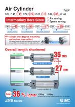
Intermediary Bore Sizes ∗1 Air saving Space saving ∗1 Same external dimensions Same external dimensions Same external dimensions Same external dimensions New A both ends tapped mounting option has been added. The overall length has been shortened by reducing the amount of tie-rod protrusion from the body end surface. Both ends tapped Overall length shortened 100 mm stroke JMB Ø 50 Both ends tapped 1.56 kg a 1.00 kg (Compared with the existing MB series model, Ø 50, 100 mm str
Open the catalog to page 1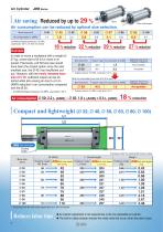
Basic Both ends tapped Air consumption can be reduced by optimal size selection. i l ti Bore size [mm] Air consumption L (ANR) Conditions/Supply pressure: 0.5 MPa Load factor: 50 %, At 100 mm stroke 18 % reduction 22 % reduction 29 % reduction 27 % reduction Example In order to move a workpiece with a weight of 37 kg, a bore size of Ø 43 or more is required. Previously, a Ø 50 bore size would have been the closest option since the next smallest size, the Ø 40, has insufficient output. However, with the newly released bore size of Ø 45, sufficient output can be obtained while also saving air due...
Open the catalog to page 2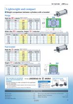
Lightweight and compact ˾ Weight comparison between cylinders with a bracket Flange MB Weight comparison Weight: Max. 49 % reduction (When mounted on the cylinder, 100 mm stroke) [kg] MB 0.95 1.28 2.01 2.62 4.7 7.79 Width: Max. 20 % reduction, Height: 16 % reduction Bore size Ø 32 Ø 40 Ø 50 Ø 63 Ø 80 Ø 100 FZ2 FZ1 Dimension comparison (When mounted on the cylinder) Foot bracket Weight: Max. 35 % reduction Bore size [mm] Ø 32 Ø 40 Ø 50 Ø 63 Ø 80 Ø 100 Weight comparison (When mounted on the cylinder, 100 mm stroke) [kg] Dimension comparison Height: 11 % reduction (When mounted on the cylinder)...
Open the catalog to page 3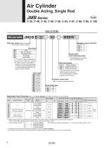
Air Cylinder Double Acting, Single Rod With auto switch With auto switch (Built-in magnet) Number of auto switches ∗ Not available without a magnet Basic Both ends tapped∗1 Axial foot bracket Rod flange Head flange Auto switch — ∗ “L,” “F,” and “G” cannot be selected for bore sizes Ø 45, Ø 56, Ø 67, and Ø 85. ∗1 In order to mount a foot bracket or flange on the both ends tapped type, it must be ordered separately. Refer to “Mounting Brackets/Part Nos.” on page 5 for order numbers. Without bracket Single knuckle joint Double knuckle joint ∗ A knuckle joint pin is not provided with the single knuckle...
Open the catalog to page 4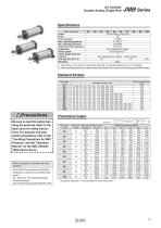
Air Cylinder Double Acting, Single Rod Specifications Bore size [mm] Action Fluid Proof pressure Max. operating pressure Min. operating pressure Ambient and fluid temperatures Lubrication Piston speed∗1 Stroke length tolerance Cushion Port size (Rc, NPT, G) Mounting Double acting, Single rod Air 1.0 MPa 0.7 MPa∗2 0.05 MPa 5 to 60 °C Not required (Non-lube) 50 to 500 mm/s∗2 +2.0 0 Non-adjustable air cushion + rubber bumper 1/8 1/4 Basic ∗1 Depending on the system configuration selected, the specified speed may not be satisfied. ∗2 Max. operating pressure and piston speed are different from those of...
Open the catalog to page 5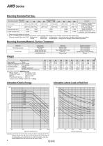
JMB Series Mounting Brackets/Part Nos. Mounting bracket Single knuckle joint Double knuckle joint 1 foot bracket, 2 hexagon nuts, and 2 flat washers 1 flange, 4 hexagon nuts, JMB-F100 and 4 flat washers I-10M 1 single knuckle joint 1 double knuckle joint, 1 pin, Y-10M 2 split pins, and 2 flat washers JMB-L100 ∗1 Order two foot brackets per cylinder. ∗2 An “A” is suffixed to the end of the part numbers of foot brackets and flanges to be mounted on the both ends tapped type. Ordering example) Bore size Ø 32 · Foot bracket JMB-L032A Included parts: 1 foot bracket and 2 hexagon socket head cap screws ·...
Open the catalog to page 6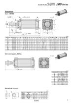
Air Cylinder Double Acting, Single Rod Dimensions Basic: JMDBB Width across flats KA Both ends tapped: JMDBA 2x4xJ Bore size
Open the catalog to page 7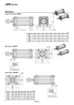
Axial foot bracket: JMDBL FN When mounted on the both ends tapped type (A) 4 x Ø FD Head flange: JMDBG FN When mounted on the both ends tapped type
Open the catalog to page 8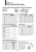
Auto Switch Mounting Auto Switch Proper Mounting Position (Detection at stroke end) and Mounting Height ≈ Hs Auto Switch Proper Mounting Position Auto Switch Mounting Height Auto switch model Bore size Bore size Auto switch model ∗ Adjust the auto switch after confirming the operating conditions in the actual setting. Min. Stroke for Auto Switch Mounting n: Number of auto switches [mm] Ø 32, Ø 40, Ø 45, Ø 50, Ø 56, Auto switch model Number of auto switches Ø 63, Ø 67, Ø 80, Ø 85, Ø 100 Bore size 2 (Different surfaces, Same surface), 1 2 (Different surfaces, Same surface), 1 2 (Different surfaces,...
Open the catalog to page 9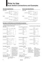
Prior to Use Auto Switch Connections and Examples Sink Input Specifications Source Input Specifications Auto switch Brown Input Auto switch Brown Input Auto switch Brown COM Auto switch Blue Connect according to the applicable PLC input specifications, as the connection method will vary depending on the PLC input specifications. Examples of AND (Series) and OR (Parallel) Connections ∗ When using solid state auto switches, ensure the application is set up so the signals for the first 50 ms are invalid. Depending on the operating environment, the product may not operate properly. 3-wire AND connection...
Open the catalog to page 10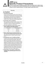
JMB Series Specific Product Precautions Be sure to read this before handling the products. Refer to the back cover for safety instructions. For actuator and auto switch precautions, refer to the “Handling Precautions for SMC Products” and the “Operation Manual” on the SMC website: https://www.smc.eu Caution 1. Allowable lateral load Lateral load that can apply to the piston rod end is limited. If a cylinder is used with a lateral load over the limit, it may cause air leakage due to abnormal friction of seals, galling of cylinder tubes and pistons, or abnormal friction of the bearing part. The...
Open the catalog to page 11All SMC catalogs and technical brochures
 In-line Type Vacuum Ejector
6 Pages
 Serie HRR
64 Pages
 Série VP/VG
33 Pages
 Série XL
27 Pages
 Série ACG/ARG/AWG
45 Pages
 Série JXC5H/6H
36 Pages
 LEJS100-X400 series
15 Pages
 JCM series
21 Pages
 PF3A7*H
40 Pages
 PF3W
PF3W34 Pages
 Compact Guide Cylinder with Lock
36 Pages
 Water Treatment
16 Pages
 Food & Packaging Industry
4 Pages
 Digital Gap Checker
26 Pages
 Vacuum Pad
16 Pages
 One-touch Fittings
224 Pages
 Soft Start-up Valve
16 Pages
 Electric Actuator
272 Pages
 Rotary Actuator
40 Pages
 Compact Guide Cylinder
18 Pages
 Compact Slide
24 Pages
 Air Cylinder
124 Pages
 LEFB, LEFG-BS series
180 Pages
 JMGP series
16 Pages
 ISO Cylinder
32 Pages
 IZD10
IZD1020 Pages
 IZH10
IZH108 Pages
 Fan Type Lonizer
28 Pages
 Check Valves
4 Pages
 Compact Cylinder/Clean series
16 Pages
 3 port solenoid Valve
74 Pages
 Vacuum Ejector Series ZM
20 Pages
 Series ZL
20 Pages
 Series CM2
92 Pages
 Series IDGA/IDG
56 Pages
 Platform Cylinder Series CXT
14 Pages
 IDH-A
IDH-A12 Pages
 CP96-C96-B
74 Pages
 CVQ
CVQ24 Pages
 HY
HY52 Pages
 VNA
VNA10 Pages
 Series MXY
28 Pages
 Series MXP
39 Pages
 Air Slide Table
132 Pages
 Compact Cylinder Series CQ2
138 Pages
 S0700
S0700112 Pages
 SYJ
SYJ96 Pages
 SY - NEW
164 Pages
 VF
VF60 Pages
 C(D)55 series
24 Pages
 C(D)Q2 series
216 Pages
 MGP series
36 Pages
 11-LEFS series
19 Pages
 LECS series
16 Pages
 LECPA series
4 Pages
 KQ series
80 Pages
 IDF series
16 Pages
 ZP series
69 Pages
 MHF series
32 Pages
 MHZ series
68 Pages
 CRB series
44 Pages
 MGJ series
7 Pages
 AC series
98 Pages
 VH series
14 Pages
 LVA series
43 Pages
 VDW series
28 Pages
 LVM series
28 Pages
 VX2 series
32 Pages
 MXH series
32 Pages
 MXF series
12 Pages
 CXW series
48 Pages
 CXS series
76 Pages
 CQS series
40 Pages
 CQM series
28 Pages
 CLQ series
36 Pages


