- Products
- Catalogs
- News & Trends
- Exhibitions
JCM series
1 /21Pages

JCM series
1 /21Pages
Catalog excerpts

New A foot type and a flange type Overall length shortened have been ve ded. added. 63 % reduction JCM Ø 40 Female thread 38 % reduction JCM Ø 40 Male thread Existing model Ø 40 (CM2 series) Height shortened New mounting band for auto switch Mounting height approx. 0.69 kg \ 0.32 kg (Compared with the existing CM2B series model, Ø 40, 50 mm stroke) Existing model
Open the catalog to page 1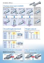
Various cover types available Direct mounting is possible. Basic (Female thread on rod cover) Mounting bracket Basic (Female thread on both covers) Mounting thread on rod side Male thread on both covers Male thread on rod cover Male mounting thread on both sides Mounting thread on rod and head sides Foot type Male mounting thread on one side Examples Rod side mounting Head side mounting g Head side mounting Overall length shortened (Compared with the existing model (CM2 series)) Overall length Female thread on rod cover Female rod end Flange type Weight reduced (Compared with the existing CM2...
Open the catalog to page 2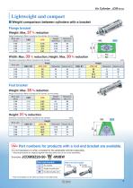
Lightweight and compact ˾ Weight comparison between cylinders with a bracket Flange bracket Weight: Max. 37 % reduction Weight comparison (When mounted on the cylinder, 50 mm stroke) Weight difference Reduction rate [ %] Width: Max. 33 % reduction, Height: Max. 30 % reduction Dimension comparison (When mounted on the cylinder) Bore size Reduction rate [%] Reduction rate [%] Foot bracket Weight: Max. 35 % reduction Weight comparison (When mounted on the cylinder, 50 mm stroke) Weight difference Reduction rate [ %] Height: 31 % reduction Dimension comparison (When mounted on the cylinder) Bore...
Open the catalog to page 3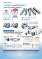
New mounting band for auto switch Mounting height shortened ened Approx. 8 mm shorter 5.3 mm Existing band Improved visibility of indicator LED Improved mounting workability There are no parts near the indicator LED, so visibility is improved. To mount the auto switch, simply insert it and position it correctly. ∗ When the auto switch mounting band is ordered at the same time as the cylinder, it will be shipped mounted on the cylinder. Mounting band Related components Auto switch Floating Joint JT Series A more compact and lightweight combination is possible by using the JCM series with a JT...
Open the catalog to page 4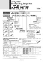
Air Cylinder Double Acting, Single Rod Without auto switch With auto switch M9BW Number of auto switches With auto switch (Built-in magnet) Mounting, Bracket Mounting Direct mounting With mounting bracket Basic (Female Axial foot thread on rod BZ cover) L Auto switch Refer to page 5 for standard strokes. Male thread on rod cover Male thread Female thread Head flange Configuration contents of cylinders with a mounting bracket Bracket-mountable cylinder models Ț JCMM Ț JCMM ҂ Ț JCMM None With mounting nut∗2 ∗1 "None" only can be selected for mounting options “B” and “BZ,” and only “D” can be selected...
Open the catalog to page 5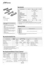
Bore size [mm] Type Double acting, Single rod Proof pressure Max. operating pressure Min. operating pressure Ambient and fluid temperatures Stroke length tolerance Piston speed∗1 Symbol Double acting, Single rod Rubber bumper Allowable kinetic Male thread energy [J] Female thread ∗ Operate the cylinder within the allowable kinetic energy. ∗1 Depending on the system configuration selected, the specified speed may not be satisfied. ∗2 Max. operating pressure and piston speed are different from those of the existing model (CM2 series). Refer to pages 13 to 15 for cylinders with auto switches. · Auto...
Open the catalog to page 6
Air Cylinder Double Acting, Single Rod Weight Male Rod End, Without Magnet Female Rod End, Without Magnet JCMBZ२-२ (Basic (Female thread on rod cover), M5 port) JCMBZ२-२F (Basic (Female thread on rod cover), M5 port) JCMBZ२२-२ (Basic (Female thread on rod cover), Rc1/8, NPT1/8 port) JCMB२-२ 0.07 (Basic (Female thread on both covers), M5 port) JCMB२२-२ (Basic (Female thread on both covers), Rc1/8, NPT1/8 port) JCMM२-२ (Male thread on both covers, M5 port) JCMBZ२२-२F 0.08 (Basic (Female thread on rod cover), Rc1/8, NPT1/8 port) JCMB२-२F 0.06 (Basic (Female thread on both covers), M5 port) JCMB२२-२F...
Open the catalog to page 7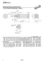
JCM Series Basic (Female Thread on Rod Cover) (BZ) JC D MBZ Bore size Port thread type Width across flats KA Width across flats B1 Port thread Female thread MM Depth A1 Port Thread: M5 Bore size Width across flats 6 length 3.5 M8 x 1.25 Width across flats 8 length 3.5 M10 x 1.25 Width across flats 8 length 3.5 M10 x 1.25 Width across flats 12 length 3.5 M14 x 1.5 Bore size Bore size Bore size ∗ ( ): Dimensions of built-in magnet type Bore size
Open the catalog to page 8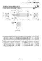
Air Cylinder Double Acting, Single Rod Basic (Female Thread on Both Covers) (B) JC D MB Bore size Port thread type Width across flats KA Width across flats B1 Port thread Female thread MM Depth A1 Port Thread: M5 Bore size Width across flats 6 length 3.5 Width across flats 8 length 3.5 Width across flats 8 length 3.5 Width across flats 12 length 3.5 Bore size Bore size Bore size
Open the catalog to page 9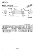
JCM Series Male Thread on Both Covers (M) JC D MM Bore size Port thread type Width across flats KA Port thread Female thread MM Depth A1 Width across flats B1 Width across flats KA Effective thread length 2 x FL Bore size Width across flats 6 length 3.5 Width across flats 8 length 3.5 Width across flats 8 length 3.5 Width across flats 12 length 3.5 Bore size Bore size Bore size Bore size
Open the catalog to page 10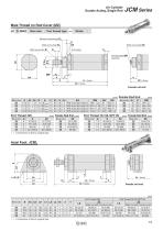
Air Cylinder Double Acting, Single Rod Male Thread on Rod Cover (MZ) JC D MMZ Bore size Port thread type Effective thread length FL Width across flats KA Width across flats B1 Width across flats KA Port thread Female thread MM Depth A1 Width across flats 6 length 3.5 M8 x 1.25 Width across flats 8 length 3.5 M10 x 1.25 Width across flats 8 length 3.5 M10 x 1.25 Width across flats 12 length 3.5 M14 x 1.5 Bore size Bore size Bore size Bore size Bore size ∗ ( ): Dimensions of built-in magnet type Axial Foot: JCML [mm] Port Thread: M5 Bore size
Open the catalog to page 11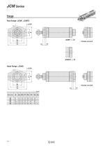
JCM Series Flange Rod flange: JCMF, JCMFZ 2 x Ø FD Head flange: JCMG 2 x Ø FD Bore size
Open the catalog to page 12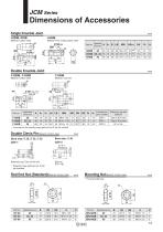
Dimensions of Accessories Single Knuckle Joint Material: Carbon steel Material: Free cutting carbon steel R1 Applicable A bore size Double Knuckle Joint Material: Carbon steel Material: Cast iron Applicable bore size Retaining ring size Split pin ∗ A knuckle pin and retaining rings (split pins for Ø 40) are included. Double Clevis Pin/Material: Carbon steel Retaining ring: Type C9 for axis ∗ Retaining rings (split pins for Ø 40) are included. Rod End Nut (Standard)/Material: Carbon steel Mounting Nut/Material: Carbon steel Applicable bore size Applicable bore size
Open the catalog to page 13All SMC catalogs and technical brochures
 In-line Type Vacuum Ejector
6 Pages
 Serie HRR
64 Pages
 Série VP/VG
33 Pages
 Série XL
27 Pages
 Série ACG/ARG/AWG
45 Pages
 Série JXC5H/6H
36 Pages
 LEJS100-X400 series
15 Pages
 JMB series
13 Pages
 PF3A7*H
40 Pages
 PF3W
PF3W34 Pages
 Compact Guide Cylinder with Lock
36 Pages
 Water Treatment
16 Pages
 Food & Packaging Industry
4 Pages
 Digital Gap Checker
26 Pages
 Vacuum Pad
16 Pages
 One-touch Fittings
224 Pages
 Soft Start-up Valve
16 Pages
 Electric Actuator
272 Pages
 Rotary Actuator
40 Pages
 Compact Guide Cylinder
18 Pages
 Compact Slide
24 Pages
 Air Cylinder
124 Pages
 LEFB, LEFG-BS series
180 Pages
 JMGP series
16 Pages
 ISO Cylinder
32 Pages
 IZD10
IZD1020 Pages
 IZH10
IZH108 Pages
 Fan Type Lonizer
28 Pages
 Check Valves
4 Pages
 Compact Cylinder/Clean series
16 Pages
 3 port solenoid Valve
74 Pages
 Vacuum Ejector Series ZM
20 Pages
 Series ZL
20 Pages
 Series CM2
92 Pages
 Series IDGA/IDG
56 Pages
 Platform Cylinder Series CXT
14 Pages
 IDH-A
IDH-A12 Pages
 CP96-C96-B
74 Pages
 CVQ
CVQ24 Pages
 HY
HY52 Pages
 VNA
VNA10 Pages
 Series MXY
28 Pages
 Series MXP
39 Pages
 Air Slide Table
132 Pages
 Compact Cylinder Series CQ2
138 Pages
 S0700
S0700112 Pages
 SYJ
SYJ96 Pages
 SY - NEW
164 Pages
 VF
VF60 Pages
 C(D)55 series
24 Pages
 C(D)Q2 series
216 Pages
 MGP series
36 Pages
 11-LEFS series
19 Pages
 LECS series
16 Pages
 LECPA series
4 Pages
 KQ series
80 Pages
 IDF series
16 Pages
 ZP series
69 Pages
 MHF series
32 Pages
 MHZ series
68 Pages
 CRB series
44 Pages
 MGJ series
7 Pages
 AC series
98 Pages
 VH series
14 Pages
 LVA series
43 Pages
 VDW series
28 Pages
 LVM series
28 Pages
 VX2 series
32 Pages
 MXH series
32 Pages
 MXF series
12 Pages
 CXW series
48 Pages
 CXS series
76 Pages
 CQS series
40 Pages
 CQM series
28 Pages
 CLQ series
36 Pages


