- Products
- Catalogs
- News & Trends
- Exhibitions
IZD10
1 /20Pages

IZD10
1 /20Pages
Catalog excerpts
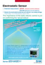
Electrostatic Sensor ć Potential measurement: ±20 kV (detected at a 50 mm distance) ±0.4 kV (detected at a 25 mm distance) ć Detects the electrostatic potential and outputs in an analog voltage. • Output voltage: 1 to 5 V (Output impedance: Approx. 100 Ω) The importance of the static electric control is put on confirming the “actual status”. tic range lectrosta kV l ±20 rage of e tions! na dditio ur cove t applica The a ns yo en ade measurem bro ial otent p Electrostatic sensor Series IZD10 ć Output: Switch output x 2 + Analog output (1 to 5 V, 4 to 20 mA) ć Minimum unit setting: 0.001 kV (at ±0.4 kV), 0.1 kV (at ±20 kV) ć Display accuracy: ±0.5% F.S. ±1 digit or less ć Detection distance correction function (adjustable in 1 mm increments) ć Supports two types of sensors (±0.4 kV and ±20 kV) through range selection Electrostatic sensor monitor Series IZE11
Open the catalog to page 1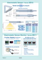
Electrostatic Sensor / Series IZD10 Small and easy to mount Dimensions (actual size) M3 screw (supplied by customer) Detection hole Sensor head Installation Distance and Detection Range IZD10-110 IZD10-510 Note 1) Potential measurement: ±0.4 kV Installation distance Detection hole Installation distance Note 2) Potential measurement: ±20 kV Detection range Electrostatic Sensor Monitor / Series IZE11 2-color display (Red/Green) Able to set the display color in 4 patterns. Mountable even with a sensor touched with each other Able to reduce the man-hour for cutting a panel. OFF ON Red Green Green...
Open the catalog to page 2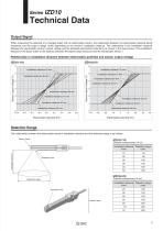
Technical Data Output Signal When measuring the potential of a charged object with an electrostatic sensor, the relationship between the electrostatic potential being measured and the output voltage varies depending on the sensor’s installation distance. The relationship in the installation distance between the electrostatic sensor’s output voltage and the detected electrostatic potential is as shown in the figure below: (The installation distance in the figure refers to the distance between the object being measured and the electrostatic sensor.) Relationship in installation distance between...
Open the catalog to page 3
Electrostatic Sensor Model 10 Electrostatic sensor Specifications Model Potential measurement Output voltage Effective detection distance Linearity ±0.4 kV (at detection distance: 25 mm)Note) ±20 kV (at detection distance: 50 mm)Note) 1 to 5 V (Output impedance: Approx. 100 Ω ) 10 to 50 mm Output delay time Power supply voltage Current consumption Operating ambient temperature Operating ambient humidity Material Vibration resistance Shock resistance Weight Compliance with EN standards EMC directive UL standard 35 to 85% Rh (with no condensation) Head case : ABS Durability 50 Hz Amplitude 1 mm...
Open the catalog to page 4
Electrostatic Sensor Series Connection Circuit and Wiring Table Connect the lead wires according to the following connection circuit and wiring table. 1. Connection circuit Electrostatic sensor Sensor amplifier Internal circuit Internal circuit Sensor head Sensor output (White) GND Sensor head case part The FG connection point is wired in common with the sensor amplifier’s fixed part. Warning Always ground the electrostatic sensor. Class-D ground 2. Wiring table Lead wire color Sensor output Be sure to apply class-D grounding to the GND terminal. In addition, a dedicated power supply is recommended...
Open the catalog to page 5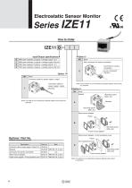
Electrostatic Sensor Monitor NPN open collector 2 outputs + Analog output 1-5 V NPN open collector 2 outputs + Analog output 4-20 mA None With connector for sensor connection PNP open collector 2 outputs + Analog output 1-5 V Connector for sensor connection PNP open collector 2 outputs + Analog output 4-20 mA None Connector cable for power supply / output Note) The connector is not connected but packed together with product for shipment. Connector cable for power supply / output None Bracket Note) The cable is not connected but packed together with product for shipment. Mounting screw (M3 x 5L)...
Open the catalog to page 6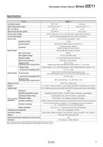
Electrostatic Sensor Monitor Series Specifications Model Rated measurement range Min. unit setting Measurement distance setting Connection sensor Power supply voltage 24 VDC, Ripple (p-p) 10% or less (with power supply polarity protection) Current consumption 50 mA or less (excluding sensor unit’s current consumption) 1 to 5 VDC (Input impedance: 1 MΩ) Sensor input With excess voltage protection (up to 26.4 V) Input protection Hysteresis mode: Variable Window comparator mode: Variable NPN or PNP open collector: 2 outputs Switch output 1 V or less (with load current of 80 mA) Residual voltage...
Open the catalog to page 7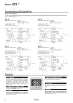
Example of Internal Circuit and Wiring Output specifications The wire colors (brown, black, white, gray and blue) shown in the circuit diagram apply when SMC’s power supply and output connection cable (Part no.: ZS-28-A) are used. NPN open collector output: 2 outputs Max. 30 V, 80 mA Residual voltage 1 V or less Analog output: 1 to 5 V Output impedance: Approx. 1 k PNP open collector output: 2 outputs Max. 80 mA Residual voltage 1 V or less Analog output: 1 to 5 V Output impedance: Approx. 1 k Analog output Main circuit Main circuit Analog output (White) Load (White) Brown NPN open collector...
Open the catalog to page 8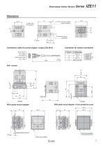
Electrostatic Sensor Monitor Series Connector for power supply/ output connection Connector for sensor connection 1.5 Connection cable for power supply / output (ZS-28-A) DC (+) Brown 5 OUT1 Black 4 OUT2 White 3 Analog output Gray 2 DC (–) Blue 1 Connector for sensor connection Pin no. 1 2 3 4 With panel mount adapter + Front protective cover With panel mount adapter Panel mount adapter + Front protective cover 8.75 Panel mount adapte
Open the catalog to page 9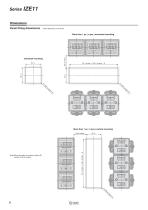
Dimensions Panel fitting dimensions More than 1 pc. (n pcs.) horizontal mounting More than 1 pc. (n pcs.) vertical mounting Note) When providing a curvature radius (R), keep it to R2 or smaller.
Open the catalog to page 10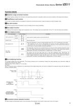
Electrostatic Sensor Monitor Series Function Details A Detection range correction function By previously inputting a distance from the sensor to the object being measured, it is possible to reduce errors due to variations in the measurement distance. B Peak/Bottom hold function This function constantly detects and updates the maximum and minimum pressure values and allows to hold the display value. C Key lock function This function prevents incorrect operations such as changing the set value accidentally. D Zero-adjust function The reading of the measured voltage can be adjusted to zero. The...
Open the catalog to page 11All SMC catalogs and technical brochures
 In-line Type Vacuum Ejector
6 Pages
 Serie HRR
64 Pages
 Série VP/VG
33 Pages
 Série XL
27 Pages
 Série ACG/ARG/AWG
45 Pages
 Série JXC5H/6H
36 Pages
 LEJS100-X400 series
15 Pages
 JMB series
13 Pages
 JCM series
21 Pages
 PF3A7*H
40 Pages
 PF3W
PF3W34 Pages
 Compact Guide Cylinder with Lock
36 Pages
 Water Treatment
16 Pages
 Food & Packaging Industry
4 Pages
 Digital Gap Checker
26 Pages
 Vacuum Pad
16 Pages
 One-touch Fittings
224 Pages
 Soft Start-up Valve
16 Pages
 Electric Actuator
272 Pages
 Rotary Actuator
40 Pages
 Compact Guide Cylinder
18 Pages
 Compact Slide
24 Pages
 Air Cylinder
124 Pages
 LEFB, LEFG-BS series
180 Pages
 JMGP series
16 Pages
 ISO Cylinder
32 Pages
 IZH10
IZH108 Pages
 Fan Type Lonizer
28 Pages
 Check Valves
4 Pages
 Compact Cylinder/Clean series
16 Pages
 3 port solenoid Valve
74 Pages
 Vacuum Ejector Series ZM
20 Pages
 Series ZL
20 Pages
 Series CM2
92 Pages
 Series IDGA/IDG
56 Pages
 Platform Cylinder Series CXT
14 Pages
 IDH-A
IDH-A12 Pages
 CP96-C96-B
74 Pages
 CVQ
CVQ24 Pages
 HY
HY52 Pages
 VNA
VNA10 Pages
 Series MXY
28 Pages
 Series MXP
39 Pages
 Air Slide Table
132 Pages
 Compact Cylinder Series CQ2
138 Pages
 S0700
S0700112 Pages
 SYJ
SYJ96 Pages
 SY - NEW
164 Pages
 VF
VF60 Pages
 C(D)55 series
24 Pages
 C(D)Q2 series
216 Pages
 MGP series
36 Pages
 11-LEFS series
19 Pages
 LECS series
16 Pages
 LECPA series
4 Pages
 KQ series
80 Pages
 IDF series
16 Pages
 ZP series
69 Pages
 MHF series
32 Pages
 MHZ series
68 Pages
 CRB series
44 Pages
 MGJ series
7 Pages
 AC series
98 Pages
 VH series
14 Pages
 LVA series
43 Pages
 VDW series
28 Pages
 LVM series
28 Pages
 VX2 series
32 Pages
 MXH series
32 Pages
 MXF series
12 Pages
 CXW series
48 Pages
 CXS series
76 Pages
 CQS series
40 Pages
 CQM series
28 Pages
 CLQ series
36 Pages


