- Products
- Catalogs
- News & Trends
- Exhibitions
CRB series
1 /44Pages

CRB series
1 /44Pages
Catalog excerpts
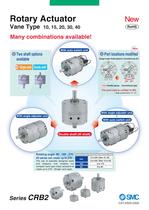
Rotary Actuator Many combinations available! With auto switch unit Double shaft Double shaft (W shaft) O Port locations modified Change in angle: Parallel piping (0°), Conventional type (25° (New Parallel piping Conventional type The port size is unified to M3. * Side ported (Size 10,15) With angle adjuster unit With auto switch unit The use of specially designed seals compact vane type rotary actuators to rotate up to 270°. (Single vane type) Rotating angle 11 Rotating angle adjustment range
Open the catalog to page 1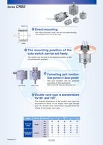
Series CRB2 Screw x 3 Direct mounting The rotary actuator body can be mounted directly. Not possible for size 10 to 40 with unit(s). CRB2 The mounting position of the auto switch can be set freely. The switch can be fixed in the desired position in the circumferential direction. Connecting port location: Side ported or Axial ported The port location can be selected according to the application. Side ported (Size 10 to 40 with unit(s) are side ported only.) Axial ported Double vane type is standardized for 90 and 100 . The outside dimensions of the double vane type are equivalent to those of the...
Open the catalog to page 2
Working Principle/How to Mount Loads series CRB2 Vane Type 1. It consists of a shaft that is integrated with the vane that slides along the inner surface of the body, and a stopper. 2. The air that is supplied from port A pushes the vane, thus creating torque in the shaft. 3. The air in the exhaust chamber discharges via port B and rotates clockwise. 4. The vane stops as it comes in contact with the stopper. 5. Similarly, when air is supplied from port B, it rotates It consists of a shaft that is integrated with the 2 vanes that slide along the inner surface and 2 stoppers. The air that is supplied...
Open the catalog to page 3
Model Selection Selection Procedures Selection Example Operating conditions are as follows: • Tentative model • Mounting orientation • Load type Static load Resistance load Inertial load • The unit for the rotating angle is radian. "| I Calculation of Moment of Inertia Calculate the Inertial moment of load. • Loads are generated from multiple parts. The inertial moment of each load is calculated, and then totaled. 2 I Calculation of Required Torque Calculate the required torque for each load type and confirm that the values fall In the effective torque range. • When the resistance load is rotated,...
Open the catalog to page 4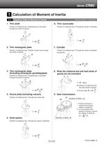
Q Calculation of Moment of Inertia 1-1 Equation Table of Moment of Inertia Position of rotational axis: Perpendicular to the shaft through the center of gravity 2. Thin rectangular plate Position of rotational axis: Parallel to side b and through 3. Thin rectangular plate (Including rectangular parallelepiped) Position of rotational axis: Perpendicular to the plate through the center of gravity 4. Round plate (Including column) Position of rotational axis: Through the center axis I: Moment of inertia m: Load mass 6. Thin round plate Position of rotational axis: Through the center of diameter...
Open the catalog to page 5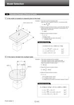
Model Selection 1-2 Calculation Example of Moment of Inertia 1 If the shaft is located at a desired point of the load: Center of gravity of load Example) 1. If the load is the thin rectangular plate: Obtain the center of gravity of load as li, a provisional shaft. 2. Obtain the actual moment of inertia I2 around the shaft, with the premise that the mass of the load itself is concentrated in the load's center of gravity point. 3. Obtain the actual moment of inertia I. L : Distance from the shaft to the center Calculation Example 2 If the load is divided into multiple loads: Example) 1. If the...
Open the catalog to page 6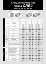
Rotary Actuator/Vane Type Basic type Vane type Port location With angle adjuster
Open the catalog to page 7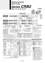
Rotary Actuator Vane Type auto switch With auto switch With auto switch With auto switch (With auto switch unit and built-in magnet) * Refer to page 33 when the auto switch unit is needed separately. Shaft type* 1 Connecting port locati on Patterned sequencing order* For details, refer to pages 19 to 30. Rotating angle Vane type Auto switch Without auto switch (Built-in magnet) * Single shaft with single flat (size 10 to 30); Key (size 40) ** Double shaft with single flat (Size 10 to 30) Long shaft key, Short shaft with single flat (Size 40) Refer to Page 4 for details of simple specials J, K,...
Open the catalog to page 8
Rotary Actuator Vane Type Single Vane Specifications Note 2) The upper numbers in this section in the table indicate the energy factor when the rubber bumper is used (at the end of the rotation), and the lower numbers indicate the energy factor when the rubber bumper is not used. Note 3) Adjustment range in the table is for 270°. For 90° and 180°, refer to page 15. Double Vane Specifications Note 1) Make sure to operate within the speed regulation range. Exceeding the maximum speed (0.3 sec/90°) can cause the unit to stick or not operate. Note 3) Adjustment range in the table is for 100°. For...
Open the catalog to page 9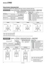
Rotary Actuator: Replaceable Shaft A shaft can be replaced with a different shaft type, except for standard shaft type Without auto switch P Size — Rotating angle Patterned sequencing order Vane type Port location Z — Made to Order For details, refer to pages 24 to 30. Round shaft Single tlat/ Round shaft Round shaft A parallel key Is used Instead of single flat for size 40. Single flat Single flat/*! Note) Dimensions and tolerance of the shaft and single flat (a parallel key for size 40) are the same as the standard. With auto switch With angle adjuster unit With auto switch Size — Rotating...
Open the catalog to page 10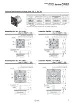
Vane Type SeneS \*r\D¿ Optional Specifications: Flange (Size: 10,15, 20, 30) Note 1 ) The flange (with countersunk head screws) is not mounted on the actuator at the time Note 2) The flange can be mounted on the rotary actuator at 60° intervals. 6 X countersunk head screw for M3 conical seat and through-hole 6 X countersunk head screw for M3 conical seat and through-hole Rotary actuator 6 X countersunk head screw for M4 conical seat and through-hole 6 X countersunk head screw for M5 conical seat and through-hole
Open the catalog to page 11All SMC catalogs and technical brochures
 In-line Type Vacuum Ejector
6 Pages
 Serie HRR
64 Pages
 Série VP/VG
33 Pages
 Série XL
27 Pages
 Série ACG/ARG/AWG
45 Pages
 Série JXC5H/6H
36 Pages
 LEJS100-X400 series
15 Pages
 JMB series
13 Pages
 JCM series
21 Pages
 PF3A7*H
40 Pages
 PF3W
PF3W34 Pages
 Compact Guide Cylinder with Lock
36 Pages
 Water Treatment
16 Pages
 Food & Packaging Industry
4 Pages
 Digital Gap Checker
26 Pages
 Vacuum Pad
16 Pages
 One-touch Fittings
224 Pages
 Soft Start-up Valve
16 Pages
 Electric Actuator
272 Pages
 Rotary Actuator
40 Pages
 Compact Guide Cylinder
18 Pages
 Compact Slide
24 Pages
 Air Cylinder
124 Pages
 LEFB, LEFG-BS series
180 Pages
 JMGP series
16 Pages
 ISO Cylinder
32 Pages
 IZD10
IZD1020 Pages
 IZH10
IZH108 Pages
 Fan Type Lonizer
28 Pages
 Check Valves
4 Pages
 Compact Cylinder/Clean series
16 Pages
 3 port solenoid Valve
74 Pages
 Vacuum Ejector Series ZM
20 Pages
 Series ZL
20 Pages
 Series CM2
92 Pages
 Series IDGA/IDG
56 Pages
 Platform Cylinder Series CXT
14 Pages
 IDH-A
IDH-A12 Pages
 CP96-C96-B
74 Pages
 CVQ
CVQ24 Pages
 HY
HY52 Pages
 VNA
VNA10 Pages
 Series MXY
28 Pages
 Series MXP
39 Pages
 Air Slide Table
132 Pages
 Compact Cylinder Series CQ2
138 Pages
 S0700
S0700112 Pages
 SYJ
SYJ96 Pages
 SY - NEW
164 Pages
 VF
VF60 Pages
 C(D)55 series
24 Pages
 C(D)Q2 series
216 Pages
 MGP series
36 Pages
 11-LEFS series
19 Pages
 LECS series
16 Pages
 LECPA series
4 Pages
 KQ series
80 Pages
 IDF series
16 Pages
 ZP series
69 Pages
 MHF series
32 Pages
 MHZ series
68 Pages
 MGJ series
7 Pages
 AC series
98 Pages
 VH series
14 Pages
 LVA series
43 Pages
 VDW series
28 Pages
 LVM series
28 Pages
 VX2 series
32 Pages
 MXH series
32 Pages
 MXF series
12 Pages
 CXW series
48 Pages
 CXS series
76 Pages
 CQS series
40 Pages
 CQM series
28 Pages
 CLQ series
36 Pages


