- Products
- Catalogs
- News & Trends
- Exhibitions
CQM series

CQM series
- Bore Sizes: Ranges from ø12 to ø100 mm.
- Standard Stroke: 5 mm to 100 mm, depending on bore size.
- Cushion Type: Rubber bumper.
- Non-Rotating Accuracy: ±0.2° or less.
- Operating Pressure: 0.1 MPa to 1.0 MPa.
- Temperature Range: -10°C to 70°C without auto switch, -10°C to 60°C with auto switch.
- Compatible with CQS and CQ2 series mounting dimensions.
- Direct load mounting capability.
- Available with or without auto switch.
- Mounting options include through-hole and both ends tapped.
- Various types available, including grommet and connector types.
- Lead wire lengths: 0.5 m, 3 m, and 5 m.
- Applicable for different voltages and wiring configurations.
- Designed for pneumatic (non-lube) applications.
- Double acting, single rod action.
- Operate within allowable load weight and speed to prevent damage.
- Made from aluminum alloy, stainless steel, and other durable materials.
- Hard anodized and chromated finishes for durability.
- Detailed part number construction for specifying bore size, stroke, and auto switch options.
- Special functions and made-to-order specifications available upon request.
- Electrical Entry: In-line and perpendicular options.
- Load Voltage: 24 VDC to 100 V AC/DC.
- Load Current: Maximums range from 20 mA to 50 mA.
- Indicator Light: Some models include a red LED indicator.
- Lead Wires: Oilproof vinyl heavy-duty cords.
- Compatibility Responsibility: Ensure system compatibility.
- Trained Personnel: Only trained personnel should operate machinery.
- Service Safety: Confirm safety before servicing machinery.
- Special Conditions: Contact SMC for use beyond specifications.
- Sudden Action: Be aware of sudden action by air cylinders.
- Protective Covers: Recommended to minimize injury risk.
- Secure Connections: Ensure all parts are securely tightened.
- Deceleration Circuits: May be required for high-speed or heavy loads.
- Pressure Drops: Consider potential drops due to power outages.
- Maximum Stroke Limits: Operate within limits to prevent damage.
- Intermediate Stops: Achieving precise stops can be challenging.
- Emergency Stops: Design systems to prevent injury or damage.
- Operate the piston within a safe range to avoid collision damage.
- Use a speed controller to gradually increase cylinder drive speed.
- Align rod shaft center with load direction to prevent damage.
- Avoid interference with external guides and prevent scratches.
- Apply grease to prevent seizure of rotating parts.
- Verify proper operation post-installation with inspections.
- Follow the instruction manual for procedures.
- Clean pipes before piping and ensure proper wrapping of pipe tape.
- Install air filters and maintain clean air supply.
- Use within specified temperature ranges and prevent freezing.
- Avoid corrosive environments and protect from dust and splashes.
- Non-lube type cylinders are factory lubricated.
- If additional lubrication is applied, it must be continued.
- Confirm specifications and avoid using outside specified range.
- Maintain a minimum separation of 40 mm between cylinders.
- Ensure proper wiring insulation and avoid wiring with power lines.
- Use appropriate screws for mounting switches.
- Avoid explosive gas atmospheres.
- Prevent accumulation of iron debris and avoid magnetic substances.
Catalog excerpts
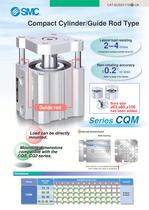
CAT.EUS20-179 B -UK Compact Cylinder/Guide Rod Type Lateral load resisting 2–4 times ∗ Compared to compact cylinder series CQ Non-rotating accuracy 0.2° or less ± Refer to page 3 for details. Bore size ø63,ø80,ø100 has been added. Guide rod External dimensions Load can be directly mounted. Slide bearing Mounting dimensions compatible with the CQS, CQ2 series. Auto switch is mountable/removable even when the plate is retracted. Variations Series Bore size (mm) Standard stroke (mm) 5 10 15 20 25 30 35 40 45 50 75 100 Cushion 12, 16 CQM 20, 25 32, 40 50, 63, 80, 100 Rubber bumper
Open the catalog to page 1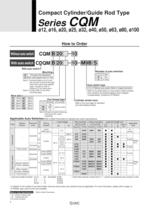
Compact Cylinder/Guide Rod Type Series CQM ø12, ø16, ø20, ø25, ø32, ø40, ø50, ø63, ø80, ø100 How to Order Without auto switch CQM B 20 With auto switch 10 CDQM B 20 10 M9B S With auto switch Number of auto switches Mounting B A S n Through-hole (Standard) Both ends tapped (ø32 to ø100) Note 1) Cylinder bodies of ø12 to ø25 are common for both B (through hole) and A (both ends tapped) types. Symbol to order is unified to “B” for those sizes. Note 2) Contact SMC for the other mounting types. Auto switch type Without auto switch (Built-in magnet cylinder) ∗ Refer to the table below for auto switch...
Open the catalog to page 2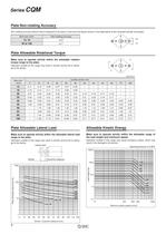
Series CQM Plate Non-rotating Accuracy Non-rotating accuracy without load is designed to be same or less than the figures shown in the table below at the retracted cylinder end (plate). Bore size (mm) Non-rotating accuracy 12, 16 ±0.2° 20 to 100 ±0.1° +θ –θ Plate Allowable Rotational Torque Make sure to operate strictly within the allowable rotation torque range to the plate. T Operation outside of this range may result in shorter service life or damage to the device. T Unit: N.m Cylinder stroke (mm) Bore size (mm) 5 10 15 20 25 30 35 40 45 50 75 100 12 0.11 0.10 0.08 0.07 0.07 0.06 – – – – –...
Open the catalog to page 4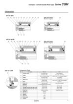
Compact Cylinder/Guide Rod Type Series CQM Construction ø12 to ø25 o t !5 !1 w !7 !2 q r !6 e !3 With auto switch (Built-in magnet) - !0 !4 - u y ø32 to ø100 o t i !1 wi !7 !2 q !0 ø50 to ø100 !5 u r !6 e !3 y !4 With auto switch (Built-in magnet) Component Parts No. 1 Description Cylinder tube 2 Collar 3 Piston Material Note Aluminum alloy Hard anodized Aluminum alloy ø12 to ø40 Anodized Aluminum alloy casted ø50 to ø100 Chromated, Coated Aluminum alloy Chromated Stainless steel ø12 to ø25 Carbon steel ø32 to ø100 Hard chrome plated 4 Piston rod 5 Plate Aluminum alloy Anodized 6 Guide rod Stainless...
Open the catalog to page 5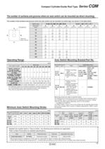
Compact Cylinder/Guide Rod Type Series CQM The number of surfaces and grooves where an auto switch can be mounted (as direct mounting). The number of the surfaces and grooves where the auto switch can be mounted, by switch type, are shown in the table below. Switch type Bore size (mm) A D-A9Ǣ(V), M9Ǣ(V), M9ǢW(V) B C D D (Mounting groove no.) (Mounting groove no.) (1) (1) (Mounting groove no.) (2) (2) D-A7Ǣ, A8Ǣ, F7Ǣ, J7Ǣ B C (2) B 20 (2) (2) (2) 25 (2) (2) (2) (2) 50 (2) 63 (2) (2) (2) (2) 80 (2) (2) (2) (2) 100 (2) (2) (2) (Mounting groove no.) (2) 40 (Mounting groove no.) (2) 32 (Mounting groove...
Open the catalog to page 13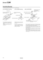
Series CQM Auto Switch Mounting To mount auto switches, follow the instruction illustrated below. ø12 to ø100/Direct mounting ø32 to ø100/Rail mounting ø40 to ø100/D-P5DWL Precise driver Auto switch mounting screw (Built-in auto switch) Auto switch mounting screw (M3 x 10l) Mounting screw for switch mounting bracket Hexagon hole cap bolt (M3 x 14l) Spring washer (normal size: 3) Switch mounting bracket Auto switch spacer Switch mounting nut Auto switch mounting nut • Use a watchmakers screwdriver with a handle 5 to 6 mm in diameter when tightening the auto switch mounting screw. Tightening torque...
Open the catalog to page 14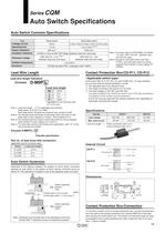
Series CQM Auto Switch Specifications Auto Switch Common Specifications Reed switch Solid state switch None Type Leakage current 3-wire: 100 µA or less, 2-wire: 0.8 mA or less Operating time 1 ms or less Note 2) 1.2 ms Impact resistance 300 m/s Insulation resistance 2 1000 m/s2 Note1) Connector style (D-A73C/A80C) and A9/A9 V style: 1000 V AC/min. (between lead wire and the case) Note 2) Except for solid state switch with timer (F7NTL) and solid state switch for strong magnetic field resistant 2-colour display (DP5DWL). 50 MΩ or more at 500 VDC Mega (between lead wire and case) Note 1) 1500 VAC...
Open the catalog to page 15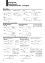
Series CQM Auto Switch Connections and Examples Basic Wiring Brown Brown Main switch circuit Load Black 2-wire (Reed) 2-wire (Solid state) Solid state 3-wire, PNP Solid state 3-wire, NPN Main switch circuit Load Brown Main switch circuit Black Indicator light, protection circuit, etc. Load Blue Blue Blue (When power supply for switch and load are separate.) Load Brown Blue Brown Brown Brown Main switch circuit Indicator light, protection circuit, etc. Main switch circuit Load Black Blue Load Blue Blue Load Examples of Connection to PLC Sink input specifications 3-wire, NPN Black Source input...
Open the catalog to page 16
Reed Switch: Direct Mounting Style D-A90(V)/D-A93(V)/D-A96(V) For details about certified products conforming to international standards, visit us at www.smcworld.com. Auto Switch Specifications Grommet Electrical entry: In-line PLC: Abbreviation for Programmable Logic Controller D-A90/D-A90V (Without indicator light) D-A90/D-A90V Auto switch part no. Applicable load Load voltage IC circuit, Relay, PLC 24 V AC/DC or less 48 V AC/DC or less 100 V AC/DC or less 50 mA 40 mA 20 mA Maximum load current Contact protection circuit None Internal resistance 1 Ω or less (including lead wire length of 3...
Open the catalog to page 17
Solid State Switch: Direct Mounting Style D-M9N(V)/D-M9P(V)/D-M9B(V) For details about certified products conforming to international standards, visit us at www.smcworld.com. Auto Switch Specifications Grommet PLC: Abbreviation of Programmable Logic Controller Ȝ 2-wire load current is reduced (2.5 to 40 mA) Ȝ Lead-free Ȝ UL certified (style 2844) lead cable is used. D-M9, D-M9V (With indicator light) Auto switch part no. D-M9N D-M9NV D-M9P D-M9PV D-M9B D-M9BV Electrical entry direction In-line Perpendicular In-line Perpendicular In-line Perpendicular 2-wire 3-wire Wiring type NPN Output type...
Open the catalog to page 18All SMC catalogs and technical brochures
 In-line Type Vacuum Ejector
6 Pages
 Serie HRR
64 Pages
 Série VP/VG
33 Pages
 Série XL
27 Pages
 Série ACG/ARG/AWG
45 Pages
 Série JXC5H/6H
36 Pages
 LEJS100-X400 series
15 Pages
 JMB series
13 Pages
 JCM series
21 Pages
 PF3A7*H
40 Pages
 PF3W
PF3W34 Pages
 Compact Guide Cylinder with Lock
36 Pages
 Water Treatment
16 Pages
 Food & Packaging Industry
4 Pages
 Digital Gap Checker
26 Pages
 Vacuum Pad
16 Pages
 One-touch Fittings
224 Pages
 Soft Start-up Valve
16 Pages
 Electric Actuator
272 Pages
 Rotary Actuator
40 Pages
 Compact Guide Cylinder
18 Pages
 Compact Slide
24 Pages
 Air Cylinder
124 Pages
 LEFB, LEFG-BS series
180 Pages
 JMGP series
16 Pages
 ISO Cylinder
32 Pages
 IZD10
IZD1020 Pages
 IZH10
IZH108 Pages
 Fan Type Lonizer
28 Pages
 Check Valves
4 Pages
 Compact Cylinder/Clean series
16 Pages
 3 port solenoid Valve
74 Pages
 Vacuum Ejector Series ZM
20 Pages
 Series ZL
20 Pages
 Series CM2
92 Pages
 Series IDGA/IDG
56 Pages
 Platform Cylinder Series CXT
14 Pages
 IDH-A
IDH-A12 Pages
 CP96-C96-B
74 Pages
 CVQ
CVQ24 Pages
 HY
HY52 Pages
 VNA
VNA10 Pages
 Series MXY
28 Pages
 Series MXP
39 Pages
 Air Slide Table
132 Pages
 Compact Cylinder Series CQ2
138 Pages
 S0700
S0700112 Pages
 SYJ
SYJ96 Pages
 SY - NEW
164 Pages
 VF
VF60 Pages
 C(D)55 series
24 Pages
 C(D)Q2 series
216 Pages
 MGP series
36 Pages
 11-LEFS series
19 Pages
 LECS series
16 Pages
 LECPA series
4 Pages
 KQ series
80 Pages
 IDF series
16 Pages
 ZP series
69 Pages
 MHF series
32 Pages
 MHZ series
68 Pages
 CRB series
44 Pages
 MGJ series
7 Pages
 AC series
98 Pages
 VH series
14 Pages
 LVA series
43 Pages
 VDW series
28 Pages
 LVM series
28 Pages
 VX2 series
32 Pages
 MXH series
32 Pages
 MXF series
12 Pages
 CXW series
48 Pages
 CXS series
76 Pages
 CQS series
40 Pages
 CLQ series
36 Pages


