- Products
- Catalogs
- News & Trends
- Exhibitions
Compact Slide
1 /24Pages

Compact Slide
1 /24Pages
Catalog excerpts
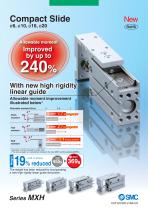
Compact Slide Allowable moment 240% With new high rigidity linear guide Allowable moment improvement illustrated below∗ Allowable moment [N·m] Pitch moment Existing model Existing model Roll moment Existing model ∗ Allowable moment caused by static load (The above graph is a comparison between the new MXH and the existing MXH6.) Existing model The weight has been reduced by incorporating a new high rigidity linear guide and piston.
Open the catalog to page 1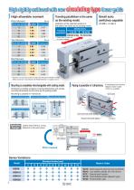
Pitch Moment Small auto switches capable (D-M9D, D-A9D) 6 10 16 20 Yaw Moment Traveling parallelism is the same as the existing model. Deflection at the extended position of the table is the same as the existing model. r Selection of a bore size cannot be made only with above allowable moment Select a bore size in accordance with “Model Selection” on pages 2 and 3. | Mounting is completely interchangeable with existing model. | Piping is possible in 3 directions. “fMcahdaen!;l(^Ogrtdeerpmo Dimensions including workpiece mounting dimensions and cylinder mounting dimensions are the same as the...
Open the catalog to page 2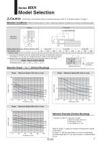
Model Selection Caution Confirmation of theoretical output is required separately. Refer to “Theoretical Output” on page 5. Selection Conditions: Follow the tables below in order to determine selection conditions and choose one selection graph. Horizontal Mounting orientation Maximum speed [mm/s] Up to 100 Up to 300 Up to 500 Up to 100 Load eccentricity L1 [mm] — 50 100 200 50 Selection graph x z c v b n m ∗ L: Overhang (the distance from the cylinder shaft centre to the load centre of gravity) The direction of L can also be a diagonal direction. (Refer to the drawing at right.) ∗ H: Distance...
Open the catalog to page 3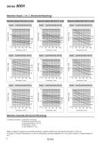
Selection Graph v to ⁄2 (Horizontal Mounting) Maximum Speed 100 mm/s or Less Maximum Speed 300 mm/s or Less Maximum Speed 500 mm/s or Less Graph v Load Eccentricity 50 mm Graph m Load Eccentricity 50 mm Graph ⁄0 Load Eccentricity 50 mm Graph b Load Eccentricity 100 mm Graph ⁄1 Load Eccentricity 100 mm Graph , Load Eccentricity 100 mm Graph n Load Eccentricity 200 mm Graph ⁄2 Load Eccentricity 200 mm Graph . Load Eccentricity 200 mm Selection Example (Horizontal Mounting) 2. Selection conditions Mounting: Horizontal Maximum speed: 500 mm/s Load eccentricity L1: 50 mm Overhang L: 30 mm Load weight...
Open the catalog to page 4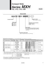
Compact Slide Compact Slide Bore size 6 Made to Order * Refer to page 5 for details. Number of auto switches — Auto switch | — | Without auto switch (Built-in magnet) | * For applicable auto switch model, refer to the table below. Cylinder stroke [mm] Refer to “Standard Stroke” on the next page. Applicable Auto Switches/Refer to the Auto Switch Guide for further information on auto switches. ** Water resistant type auto switches can be mounted on the above models, but in such case SMC cannot Please consult with SMC regarding water resistant type with the above model numbers. guarantee water...
Open the catalog to page 5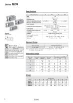
ojtgj Made to Order (Refer to pages 16 to 18 for details.) Standard Stroke Note) Intermediate strokes are available with “Made to Order"' model (-XC19). (For details, refer to page 18.) Theoretical Output
Open the catalog to page 6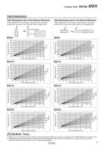
Compact Slide Table Displacement Table Displacement due to Pitch Moment (Reference) Table Displacement due to Yaw Moment (Reference) Table displacement (arrow) when a load acts upon the section marked with the arrow at the full stroke of the Compact Slide Table displacement (arrow) when a load acts upon the section marked with the arrow at the full stroke of the Compact Slide 1. Selection of a bore size cannot be made only with above graphs. Select a bore size in accordance with “Model Selection” on page 2 and 3. 2. Displacement may increase after an impact load has been applied. When the table...
Open the catalog to page 7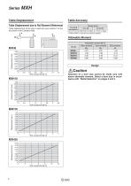
Table displacement (at A) when a load acts upon section F at the full stroke of the Compact Slide Table Accuracy Traveling parallelism * Values when no load and no pressure applied. Allowable Moment Caution Selection of a bore size cannot be made only with above allowable moment. Select a bore size in accordance with “Model Selection” on pages 2 and 3.
Open the catalog to page 8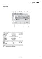
Compact Slide Series MXH Note) The MXH series cannot be disassembled.
Open the catalog to page 9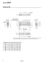
3 x M4 x 0.7 through Pilot hole dia ø3.3 6 x ø6 counterbore depth 3.3 Plug for port: MXH-P (4 pcs.) Note 1) Refer to “Specific Product Precautions” for mounting of the Compact Slide and a workpiece. Note 2) When changing the port location, please order a new port plug: MXH-P (2 pcs.)
Open the catalog to page 10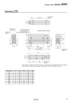
Compact Slide Series MXH Note 1) Refer to “Specific Product Precautions” for mounting of the Compact Slide and a workpiece. Note 2) When changing the port location, please order a new port plug: MXH-P (2 pcs.)
Open the catalog to page 11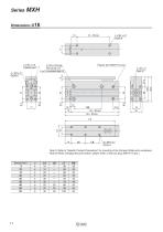
Note 1) Refer to “Specific Product Precautions” for mounting of the Compact Slide and a workpiece. Note 2) When changing the port location, please order a new port plug: MXH-P (2 pcs.)
Open the catalog to page 12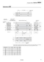
Compact Slide 3 x M6 x 1.0 through Pilot hole dia ø5.1 6 x ø9.3 counterbore depth 8 Plug for port: MXH-P (4 pcs.) Note 1) Refer to “Specific Product Precautions” for mounting of the Compact Slide and a workpiece. Note 2) When changing the port location, please order a new port plug: MXH-P (2 pcs.) Stroke [mm] 5 10 15 20 25 30 40 50 60
Open the catalog to page 13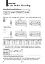
ISeries MXH Auto Switch Mounting Minimum Stroke for Auto Switch Mounting Note 1) Negative figures in the table W indicate that an auto switch is mounted inward from the edge of the cylinder body. Note 2) In the case of models with 5 and 10 strokes, the auto switch may not turn off due to operating range or two auto switches may turn on simultaneously. Fix auto switches outside 1 to 4 mm further than the values in the table above. (If one auto switch is used, make sure that it turns ON and OFF properly; If two auto switches are used, make sure that both auto switches turn ON.) Note 3) ( ) in column...
Open the catalog to page 14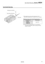
Auto Switch Mounting Series MXH • When tightening the auto switch mounting screw, use a watchmaker’s screwdriver with a handle 5 to 6 mm in diameter. Tightening Torque of Auto Switch Mounting Screw [N-m; Auto switch model Note) When used with side ported type, it is not possible to mount the D-A9DV/M9DV type on the side to which the piping is connected.
Open the catalog to page 15All SMC catalogs and technical brochures
 In-line Type Vacuum Ejector
6 Pages
 Serie HRR
64 Pages
 Série VP/VG
33 Pages
 Série XL
27 Pages
 Série ACG/ARG/AWG
45 Pages
 Série JXC5H/6H
36 Pages
 LEJS100-X400 series
15 Pages
 JMB series
13 Pages
 JCM series
21 Pages
 PF3A7*H
40 Pages
 PF3W
PF3W34 Pages
 Compact Guide Cylinder with Lock
36 Pages
 Water Treatment
16 Pages
 Food & Packaging Industry
4 Pages
 Digital Gap Checker
26 Pages
 Vacuum Pad
16 Pages
 One-touch Fittings
224 Pages
 Soft Start-up Valve
16 Pages
 Electric Actuator
272 Pages
 Rotary Actuator
40 Pages
 Compact Guide Cylinder
18 Pages
 Air Cylinder
124 Pages
 LEFB, LEFG-BS series
180 Pages
 JMGP series
16 Pages
 ISO Cylinder
32 Pages
 IZD10
IZD1020 Pages
 IZH10
IZH108 Pages
 Fan Type Lonizer
28 Pages
 Check Valves
4 Pages
 Compact Cylinder/Clean series
16 Pages
 3 port solenoid Valve
74 Pages
 Vacuum Ejector Series ZM
20 Pages
 Series ZL
20 Pages
 Series CM2
92 Pages
 Series IDGA/IDG
56 Pages
 Platform Cylinder Series CXT
14 Pages
 IDH-A
IDH-A12 Pages
 CP96-C96-B
74 Pages
 CVQ
CVQ24 Pages
 HY
HY52 Pages
 VNA
VNA10 Pages
 Series MXY
28 Pages
 Series MXP
39 Pages
 Air Slide Table
132 Pages
 Compact Cylinder Series CQ2
138 Pages
 S0700
S0700112 Pages
 SYJ
SYJ96 Pages
 SY - NEW
164 Pages
 VF
VF60 Pages
 C(D)55 series
24 Pages
 C(D)Q2 series
216 Pages
 MGP series
36 Pages
 11-LEFS series
19 Pages
 LECS series
16 Pages
 LECPA series
4 Pages
 KQ series
80 Pages
 IDF series
16 Pages
 ZP series
69 Pages
 MHF series
32 Pages
 MHZ series
68 Pages
 CRB series
44 Pages
 MGJ series
7 Pages
 AC series
98 Pages
 VH series
14 Pages
 LVA series
43 Pages
 VDW series
28 Pages
 LVM series
28 Pages
 VX2 series
32 Pages
 MXH series
32 Pages
 MXF series
12 Pages
 CXW series
48 Pages
 CXS series
76 Pages
 CQS series
40 Pages
 CQM series
28 Pages
 CLQ series
36 Pages


