


CLQ series

CLQ series
- Locking Mechanism: Allows locking at any position within the stroke, preventing drops during mid-stroke emergency stops and accommodating external stopper positions.
- Locking Directions: Options for extension and retraction locking, selectable upon order.
- Compact Design: The lock unit is integrated within the cylinder's dimensions for a low profile.
- Manual Unlocking: Facilitates easy manual unlocking for operational flexibility.
- Bore Sizes: ø20, ø25, ø32, ø40, ø50, ø63, ø80, ø100 mm.
- Operating Pressure: Maximum 1.0 MPa, minimum 0.2 MPa.
- Temperature Range: -10 to 70°C without auto switch, -10 to 60°C with auto switch.
- Locking Pressure: 0.05 MPa or less for locking, 0.2 MPa or more for unlocking.
- Types: Through holes, double end taps, foot type, front flange type, rear flange type, double clevis type.
- Auto Switch: Available with or without, with various mounting options and lead wire lengths.
- Materials: Made from aluminum alloy, carbon steel, stainless steel, and other durable materials.
- Locking System: Utilizes a lock ring and brake spring mechanism for secure locking.
- Impact Absorption: For high-speed or heavy load operations, consider installing a deceleration circuit or an external shock absorber.
- Pressure Drop: Install safety equipment to prevent damage or injury from pressure drops.
- Power Loss: Implement measures to protect against injury and equipment damage in case of power loss.
- Sudden Lurching Prevention: Design circuits to prevent sudden lurching of driven objects.
- Emergency Stops: Ensure machinery design prevents injury or damage during emergency stops.
- Restart After Stops: Design machinery to prevent injury or damage upon restart after an emergency stop.
- Corrosion and Dust: Avoid using in corrosive environments. Protect equipment in dusty or splash-prone areas.
- Magnetic Fields: Avoid operating auto switches in strong magnetic fields.
- Regular Maintenance: Follow the instruction manual to prevent malfunction and damage.
- Compressed Air Handling: Ensure proper removal of equipment and exhaust of compressed air before maintenance.
- Drain Flushing: Regularly remove drainage from air filters.
- Pipe Preparation: Thoroughly clean pipes before connection to prevent debris entry.
- Air Quality: Use clean air and install air filters, after-coolers, or water separators to prevent equipment malfunction.
- Temperature Range: Operate within specified fluid and ambient temperature ranges to prevent freezing and damage.
- Specifications Compliance: Use products within specified load current, voltage, temperature, and impact ranges.
- Magnetic Interference: Maintain a minimum separation of 40mm between auto switch cylinders to prevent malfunction.
- Wiring Considerations: Keep wiring short to prevent excess current and ensure proper insulation.
- Surge Voltage: Use protection boxes for loads generating surge voltage.
- Interlock Circuits: Implement double interlock systems for high reliability.
- Explosive Atmospheres: Do not use auto switches in explosive gas environments.
- Magnetic Fields: Avoid areas with strong magnetic fields to prevent malfunction.
- Water Exposure: Avoid continuous water exposure to prevent malfunction.
- Avoid using auto switches in environments with oil, chemicals, or temperature cycles. Consult SMC for guidance in such conditions to prevent insulation issues or malfunction.
- Reed switches should not be exposed to excessive impact shock (300m/s² or more) as it may cause malfunction.
- Solid state switches should be kept away from surge-generating units to prevent damage.
- Prevent accumulation of iron waste or proximity to magnetic substances to avoid loss of magnetic force.
- Regularly tighten switch mounting screws and check for lead wire damage to prevent malfunction.
- Ensure the green LED on the 2-color indicator type switch is lit when stopped at the correct position.
- Do not use for intermediate cylinder stops as it may shorten service life.
- Select the correct locking direction; the cylinder does not generate holding force opposite to the locking direction.
- Ensure load weight, maximum speed, and eccentric distance are within specified limits to avoid damage.
- For sizes ø20 to ø32, manual unlocking involves removing the dust cover and using a flat head screwdriver or unlocking bolt.
- Ensure no external force is applied during unlocking to prevent sudden movement.
- Operate with clean, unlubricated air to maintain performance.
- Do not apply grease to the piston rod or disassemble the lock unit to avoid reducing locking performance.
- SMC Corporation and its subsidiaries are listed with contact details for various countries, providing support and sales information.
Catalog excerpts
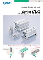
CAT.ES20-155 A Compact Cylinder with Lock Series ø63, ø80, ø100 CLQ ø20, ø25, ø32, ø40, ø50, Maintains cylinder position when supply pressure falls or residual pressure is released Drop prevention for press fitting jig, etc. Drop prevention for lifter Holding a clamped condition Retraction locking Retraction locking Extension locking LO CK CK LO LO CK
Open the catalog to page 1
Series CLQ Locking is possible at any position within the entire stroke Can be locked at any desired position • Drop prevention for mid-stroke emergency stops • Locking position can be changed to accommodate external stopper positions and thickness of clamped work pieces Drop prevention for press fitting jig, etc. Extension locking Drop prevention for lifter Retraction locking Holding a clamped condition Retraction locking LO CK CK LO LO CK Simple construction/Simple and reliable locking system Unlocked Locked Brake spring Lock ring Piston rod FREE LOCK Pivot CK LO Features 1 Load direction Fulcrum...
Open the catalog to page 2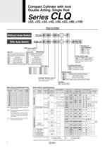
Compact Cylinder with lock Double Acting: Single Rod Series ø40, ø50, ø63, ø80, ø100 CLQ ø20, ø25, ø32, How to Order CLQ B 40 30 D F CDLQ B 40 30 D F Without Auto Switch With Auto Switch A73 S Number of auto switches With auto switch Nil S n (built-in magnet) ø20, ø25 Mounting ø32 to ø100 Through hole/Double end B tapped common (standard) Foot type L Front flange type F Rear flange type G Double clevis type D Through hole (standard) Double end tapped Foot type Front flange type Rear flange type Double clevis type B A L F G D Auto switch type Nil Locking direction Bore size 20mm 25mm 32mm 40mm...
Open the catalog to page 4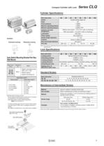
Compact Cylinder with Lock Series CLQ Cylinder Specifications 20 Bore size (mm) Action Fluid Proof pressure Maximum operating pressure Minimum operating pressure Extension locking Retraction locking W 32 40 50 63 80 100 Double acting single rod Air 1.5MPa 1.0MPa 0.2MPa Note) Without auto switch: –10 to 70°C (with no freezing) With auto switch: –10 to 60°C (with no freezing) Non-lube 50 to 500mm/s +1.0 mm 0 None or rubber bumper JIS class 2 M5 x 0.8 Rc 1/8 Rc 1/4 Rc 3/8 Ambient and fluid temperature Symbols 25 Lubrication Piston speed Stroke length tolerance Cushion Rod end thread tolerance Port...
Open the catalog to page 5
Series CLQ Construction/ø20 to ø32 A B A' B' Extension locking Without magnet When shipped Section A-A' Retraction locking Section B-B' With bumper Rod end male threads Note) The sectional drawing above shows the locked condition. (A bolt is used to maintain the cylinder in the unlocked condition when shipped.) Parts list No. 1 2 3 Description Material Note Cylinder tube Aluminum alloy Hard anodized Lock body Aluminum alloy Hard anodized Intermediate collar 4 5 Lock ring 6 Piston rod 7 8 9 Pivot Brake spring Dust cover holding bolt Aluminum alloy No. Description Material Note Oil-impregnated...
Open the catalog to page 8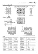
Compact Cylinder with Lock Series CLQ Construction/ø40 to ø100 A B A' B' Extension locking Without magnet Section A-A' Section B-B' (double end tapped) Retraction locking Section B-B' (through hole) With bumper Rod end male threads Note) The sectional drawing above shows the locked condition. Parts list Material Note No. 1 2 3 4 5 Cylinder tube Aluminum alloy Hard anodized Bumper A Lock body Aluminum alloy Hard anodized Intermediate collar Aluminum alloy Chromated Carbon steel Heat treated Steel wire Zinc chromated 6 Collar Aluminum alloy ø40: Hard anodized 17 18 19 20 21 22 23 24 25 26 27 28...
Open the catalog to page 9
Series CLQ Dimensions/ø20, ø25 Standard type (through hole/double end tapped): C२LQB20/25 Rod end male threads H1 Rod end nut H2 C1 X L1 Retraction locking LOCK VH1 W1 M5 x 0.8 unlocking port Dust cover (manual unlocking unit) (unlocks when pressurized) Extension locking LOCK M5 x 0.8 Front cylinder port Q M5 x 0.8 unlocking port (unlocks when pressurized) H effective thread depth C 5.5 2-ø5.4 through 2 x 2-ø9 counter bore depth 7 VH U 6.5 M E øD VV øI 3.2 2 x 2-M5 x 0.8 16 L W G M5 x 0.8 Rear cylinder port 3.2 16 K M E S Dust cover (manual unlocking unit) B + Stroke A + Stroke (mm) Bore size...
Open the catalog to page 10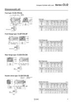
CLQ Series Compact Cylinder with Lock Dimensions/ø20, ø25 Foot type: CLQL/CDLQL G Special cap bolt B + Stroke LH LY S L Foot type (mm) Without auto switch 3.2 4-ø6.6 LX LZ Rod end nut L1 20 25 5 to 50 5 to 50 A 68.2 75.7 G L1 20 25 4 Stroke range Bore size (mm) X 5.8 X 5.8 LS + Stroke A + Stroke Bore size (mm) 27 31 L B 19.5 22.5 With auto switch B 29.5 32.5 LS A 34.5 78.2 38.5 85.7 LH LX LY LZ 24 26 14.5 28.5 15 32.5 48 52 42 46 62 66 X LS 44.5 48.5 S 9.2 45.2 10.7 49.2 FV S Front flange type: CLQF/CDLQF Front flange type 8 L FX FZ B + Stroke G A + Stroke (mm) Bore size (mm) Stroke range 20...
Open the catalog to page 11
Series CLQ Dimensions/ø32 Double end tapped: C२LQA32 3.2 16 2 x 4-M5 x 0.8 3.2 16 Standard type (through hole): C२LQB32 Extension locking LOCK Rc 1/8 unlocking port (unlocks when pressurized) 42.5 Rc 1/8 Rear cylinder port Approx. 31.5 7.5 7.5 22.5 M8 x 1.25 Effective thread depth 13 2-ø5.4 through 2 x 2-ø9 counter bore depth 7 ø6 0 45 11 27 34 22 ø16 6.5 9 Rc 1/8 Front cylinder port Minimum lead wire bending radius 10 7 Retraction locking 32 Auto switch D-A7, A8 48 .1 Dust cover (manual unlocking unit) B + Stroke A + Stroke 14 34 45 61.7 4.5 LOCK 22.5 13.5 Rc 1/8 unlocking port (unlocks when...
Open the catalog to page 12
Compact Cylinder with Lock Series CLQ Dimensions/ø32 Foot type: C२LQL32 17 B + Stroke 32 11.2 5.8 3.2 30 57 60.2 Special cap bolt 5.8 4 LS + Stroke A + Stroke 4-ø6.6 57 71 11.2 Foot type (mm) Bore size (mm) 32 Rod end nut Stroke range 10 to 50 75, 100 38.5 Without auto switch A 79.2 89.2 B 23 33 LS 39 49 With auto switch A B LS 89.2 33 49 34 48 54.2 Front flange type: C२LQF32 8 17 32 4-ø5.5 56 65 B + Stroke A + Stroke Front flange type Bore size (mm) 32 Rod end nut Stroke range 10 to 50 75, 100 38.5 (mm) Without auto switch With auto switch A 72 82 B 23 33 A B 82 33 54.2 48 34 Rear flange type:...
Open the catalog to page 13All SMC catalogs and technical brochures
 In-line Type Vacuum Ejector
6 Pages
 Serie HRR
64 Pages
 Série VP/VG
33 Pages
 Série XL
27 Pages
 Série ACG/ARG/AWG
45 Pages
 Série JXC5H/6H
36 Pages
 LEJS100-X400 series
15 Pages
 JMB series
13 Pages
 JCM series
21 Pages
 PF3A7*H
40 Pages
 PF3W
PF3W34 Pages
 Compact Guide Cylinder with Lock
36 Pages
 Water Treatment
16 Pages
 Food & Packaging Industry
4 Pages
 Digital Gap Checker
26 Pages
 Vacuum Pad
16 Pages
 One-touch Fittings
224 Pages
 Soft Start-up Valve
16 Pages
 Electric Actuator
272 Pages
 Rotary Actuator
40 Pages
 Compact Guide Cylinder
18 Pages
 Compact Slide
24 Pages
 Air Cylinder
124 Pages
 LEFB, LEFG-BS series
180 Pages
 JMGP series
16 Pages
 ISO Cylinder
32 Pages
 IZD10
IZD1020 Pages
 IZH10
IZH108 Pages
 Fan Type Lonizer
28 Pages
 Check Valves
4 Pages
 Compact Cylinder/Clean series
16 Pages
 3 port solenoid Valve
74 Pages
 Vacuum Ejector Series ZM
20 Pages
 Series ZL
20 Pages
 Series CM2
92 Pages
 Series IDGA/IDG
56 Pages
 Platform Cylinder Series CXT
14 Pages
 IDH-A
IDH-A12 Pages
 CP96-C96-B
74 Pages
 CVQ
CVQ24 Pages
 HY
HY52 Pages
 VNA
VNA10 Pages
 Series MXY
28 Pages
 Series MXP
39 Pages
 Air Slide Table
132 Pages
 Compact Cylinder Series CQ2
138 Pages
 S0700
S0700112 Pages
 SYJ
SYJ96 Pages
 SY - NEW
164 Pages
 VF
VF60 Pages
 C(D)55 series
24 Pages
 C(D)Q2 series
216 Pages
 MGP series
36 Pages
 11-LEFS series
19 Pages
 LECS series
16 Pages
 LECPA series
4 Pages
 KQ series
80 Pages
 IDF series
16 Pages
 ZP series
69 Pages
 MHF series
32 Pages
 MHZ series
68 Pages
 CRB series
44 Pages
 MGJ series
7 Pages
 AC series
98 Pages
 VH series
14 Pages
 LVA series
43 Pages
 VDW series
28 Pages
 LVM series
28 Pages
 VX2 series
32 Pages
 MXH series
32 Pages
 MXF series
12 Pages
 CXW series
48 Pages
 CXS series
76 Pages
 CQS series
40 Pages
 CQM series
28 Pages


