- Products
- Catalogs
- News & Trends
- Exhibitions
CLJ
1 /65Pages

CLJ
1 /65Pages
Catalog excerpts
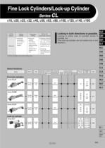
Fine Lock Cylinders/Lock-up Cylinder Locking in both directions is possible. Locking in either side of cylinder stroke is (The lock-up cylinder can be locked only in one (Lock-up cylinders are spring locking only.) Series Variations Fine lock cylinders Lock-up cylinder Bore size
Open the catalog to page 1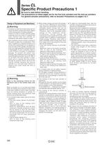
Specific Product Precautions 1 Be sure to read before handling. The precautions on these pages are for the fine lock cylinders and the lock-up cylinders. For general actuator precautions, refer to Actuator Precautions on pages 3 to 7. Design of Equipment and Machinery 1. Construct so that the human body will not come into direct contact with driven objects or the moving parts of locking cylinders. If there is a risk of contact, provide safety measures such as a cover or a system that uses sensors that will activate an emergency stop before contact is made. 2. Use a balance circuit in which lurching...
Open the catalog to page 2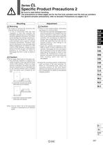
Specific Product Precautions 2 Be sure to read before handling. The precautions on these pages are for the fine lock cylinders and the lock-up cylinders. For general actuator precautions, refer to Actuator Precautions on pages 3 to 7. load with the lock released. • If this is performed with the lock engaged, a load that exceeds the allowable rotational force or holding force would be applied to the piston rod, which could damage the locking mechanism. The fine lock and Series CL1 with 040 to 0100 cylinders have a built-in manual unlocking mechanism. Therefore, they can be maintained in the unlocked...
Open the catalog to page 3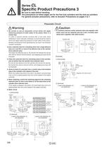
Specific Product Precautions 3 Be sure to read before handling. The precautions on these pages are for the fine lock cylinders and the lock-up cylinders. For general actuator precautions, refer to Actuator Precautions on pages 3 to 7. Pneumatic Circuit 1.Be certain to use an pneumatic circuit which will apply balancing pressure to both sides of the piston when in a locked stop. In order to prevent cylinder lurching after a lock stop, when restarting or when manually unlocking, a circuit should be used to which will apply balancing pressure to both sides of the piston, thereby canceling the force...
Open the catalog to page 4
Specific Product Precautions 4 Be sure to read before handling. The precautions on these pages are for the fine lock cylinders and the lock-up cylinders. For general actuator precautions, refer to Actuator Precautions on pages 3 to 7. How to Manually Disengage the Lock and Change from the Unlocked to the Locked State The lock is manually disengaged at the time the cylinder is shipped from the factory. Because the lock will not operate in this state, make sure to change it to the locked state before operation, after having adjusted the axial center for How to Change from Unlocked to Locked State...
Open the catalog to page 5
P0595-P0668-E.qxd 08.11.17 2:57 PM Page 600 Prior to Use Construction Principle/Applicable Series: CLJ2, CLM2, CLG1, MLGC Spring locking type Tapered brake piston Release port Pressurized lock port (Plug with breathing hole for spring lock) Brake arm Fulcrum A (Rotary axis) Roller Air pressure supply Brake shoe Brake spring Application point C Air pressure exhaust Power point B Unlocked state Locked state Spring locking (Exhaust locking) The spring force that is applied to the tapered brake piston becomes amplified through the wedge effect. This force becomes further amplified to the power of...
Open the catalog to page 6
Fine Lock Cylinder Double Acting, Single Rod With auto switch With auto switch* (Built-in magnet) Mounting style Bore size Built-in Magnet Cylinder Model If a built-in magnet cylinder without an auto switch is required, there is no need to enter the symbol for the auto switch. Port location Refer to page 602 for details. Number of auto switches Auto switch Without auto switch 1 For the applicable auto switch model, refer to the table below. Lock operation Applicable AutO Switch/Refer to pages 1719 to I827 for further information on auto switches. 1 Water resistant type auto switches can be mounted...
Open the catalog to page 7
Provided with a compact lock intermediate stop, emergency stop, and drop prevention. Locking in both directions The piston rod can be locked in either direction of its cylinder stroke. Maximum piston speed: that it is within the allowable kinetic energy Head Cover Port Location Either perpendicular to the cylinder axis or in-line with the cylinder axis is available for basic style. Made to Order Specifications (For details, refer to page 1836.) Refer to pages 608 to 610 for cylinders with auto switches. ■ Minimum auto switch mounting stroke ■ Proper auto switch mounting position (detection at...
Open the catalog to page 8
Fine Lock Cylinder Double Acting, Single Rod SeneS A Caution/Allowable Kinetic Energy when Locking * Mounting nut and rod end nut are included in the basic mass. ** Mounting nut is not included in double clevis style. Stopping Accuracy (Not including tolerance of control system.) (mm) Solenoid valve: Lock port mounting Recommended Pneumatic Circuit/Caution on Handling ■ For detailed specifications of the fine . lock cylinder, Series CLJ2 mentioned ' above, refer to pages 596 to 599. ' . In terms of specific load conditions, this allowable kinetic energy is equivalent to a load of 3.7 kg in mass,...
Open the catalog to page 9
Construction (Not able to disassemble) Spring locking (Exhaust locking) Spring and pneumatic locking Pneumatic locking (Pressure locking) Component Parts
Open the catalog to page 10
P0595-P0668-E.qxd 08.11.17 2:57 PM Page 605 Fine Lock Cylinder Double Acting, Single Rod Series CLJ2 Basic Style (B) CLJ2B16- E -D P ø Silencer CLJ2 Spring lock CLM2 M5 x 0.8 pressurized locking port Pneumatic locking and spring and pneumatic locking Piping port M5 x 0.8 Manual unlocking cam M5 x 0.8 unlocking port Unlocked when pressurized Lock nut CL1 Head cover port in axial direction (R) M5 x 0.8 Rod side cylinder port M5 x 0.8 Head side cylinder port M14 x 1.0 MLGC CNG MNB ø 0 18.3 –0.3 ø M6 x 1.0 Width across flats 10 CLG1 18.3 CNA 0 –0.3 CNS 111 + Stroke 150 + Stroke CLS CLQ RLQ Axial...
Open the catalog to page 11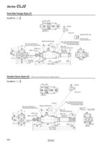
P0595-P0668-E.qxd Series 08.11.17 2:57 PM Page 606 CLJ2 Rod Side Flange Style (F) CLJ2F16- E -D P ø8 Silencer Spring lock Piping port M5 x 0.8 Head cover port in axial direction (R) Manual unlocking cam M5 x 0.8 pressurized locking port Pneumatic locking and spring and pneumatic locking M5 x 0.8 unlocking port Unlocked when pressurized M5 x 0.8 Lock nut Rod side cylinder port M14 x 1.0 M6 x 1.0 M5 x 0.8 ø Width across flats 10 0 18.3–0.3 ø Head side cylinder port 0 18.3–0.3 2 x ø5.5 Mounting hole Double Clevis Style (D) CLJ2D16- 111 + Stroke 150 + Stroke ∗ Clevis pin and retaining ring are shipped...
Open the catalog to page 12All SMC catalogs and technical brochures
 In-line Type Vacuum Ejector
6 Pages
 Serie HRR
64 Pages
 Série VP/VG
33 Pages
 Série XL
27 Pages
 Série ACG/ARG/AWG
45 Pages
 Série JXC5H/6H
36 Pages
 LEJS100-X400 series
15 Pages
 JMB series
13 Pages
 JCM series
21 Pages
 PF3A7*H
40 Pages
 PF3W
PF3W34 Pages
 Compact Guide Cylinder with Lock
36 Pages
 Water Treatment
16 Pages
 Food & Packaging Industry
4 Pages
 Digital Gap Checker
26 Pages
 Vacuum Pad
16 Pages
 One-touch Fittings
224 Pages
 Soft Start-up Valve
16 Pages
 Electric Actuator
272 Pages
 Rotary Actuator
40 Pages
 Compact Guide Cylinder
18 Pages
 Compact Slide
24 Pages
 Air Cylinder
124 Pages
 LEFB, LEFG-BS series
180 Pages
 JMGP series
16 Pages
 ISO Cylinder
32 Pages
 IZD10
IZD1020 Pages
 IZH10
IZH108 Pages
 Fan Type Lonizer
28 Pages
 Check Valves
4 Pages
 Compact Cylinder/Clean series
16 Pages
 3 port solenoid Valve
74 Pages
 Vacuum Ejector Series ZM
20 Pages
 Series ZL
20 Pages
 Series CM2
92 Pages
 Series IDGA/IDG
56 Pages
 Platform Cylinder Series CXT
14 Pages
 IDH-A
IDH-A12 Pages
 CP96-C96-B
74 Pages
 CVQ
CVQ24 Pages
 HY
HY52 Pages
 VNA
VNA10 Pages
 Series MXY
28 Pages
 Series MXP
39 Pages
 Air Slide Table
132 Pages
 Compact Cylinder Series CQ2
138 Pages
 S0700
S0700112 Pages
 SYJ
SYJ96 Pages
 SY - NEW
164 Pages
 VF
VF60 Pages
 C(D)55 series
24 Pages
 C(D)Q2 series
216 Pages
 MGP series
36 Pages
 11-LEFS series
19 Pages
 LECS series
16 Pages
 LECPA series
4 Pages
 KQ series
80 Pages
 IDF series
16 Pages
 ZP series
69 Pages
 MHF series
32 Pages
 MHZ series
68 Pages
 CRB series
44 Pages
 MGJ series
7 Pages
 AC series
98 Pages
 VH series
14 Pages
 LVA series
43 Pages
 VDW series
28 Pages
 LVM series
28 Pages
 VX2 series
32 Pages
 MXH series
32 Pages
 MXF series
12 Pages
 CXW series
48 Pages
 CXS series
76 Pages
 CQS series
40 Pages
 CQM series
28 Pages
 CLQ series
36 Pages


