- Products
- Catalogs
- News & Trends
- Exhibitions
cep

cep
- Resolution and Accuracy: CEP1 offers 0.01 mm resolution with ±0.02 mm accuracy; CE1 offers 0.1 mm resolution with ±0.2 mm accuracy.
- Output Function: RS-232C BCD with multiple output points and bank switching capabilities.
- Power Supply: Operates on 12 to 24 VDC.
- Seal Material: Customizable options available.
- Mounting: Flexible auto switch mounting on three surfaces.
- Includes high precision and standard stroke reading cylinders with special scrapers for fluid environments.
- Full stroke range measurement with home position reset capability.
- Apply load axially to avoid rotational torque.
- Protect from liquids and strong magnetic fields.
- Use appropriate counters to prevent miscounting.
- Used in die assembly detection, dimension inspection, and hydraulic cylinder press-in confirmation.
- Utilizes an MR element for detecting rod movement, outputting as a pulse signal.
- Use shield wires, separate power sources, noise filters, and ferritic cores to minimize interference.
- Offers various mounting styles, bore sizes, and sensor cable lengths.
- Auto switch options include solid state and reed switches.
- CEP1 operates with air, proof pressure of 1.5 MPa, and a maximum operating pressure of 1.0 MPa.
- Piston speed ranges from 50 to 300 mm/s, with an operating temperature of 0 to 60°C.
- Includes solid state and reed types, with water-resistant options available.
- Direct rod side tapped, foot, or rod side flange styles available.
- Magnetic scale rod and sensor head with incremental position detection.
- Made from aluminum alloy, carbon steel, and stainless steel with durable coatings.
- Fluororubber seals and extension cables available as made-to-order options.
- Includes models CEU5, CEU5-D, CEU5P, CEU5P-D, CEU5B, CEU5B-D, CEU5PB, and CEU5PB-D.
- Features a 6-digit LCD display, memory holding, and various input/output configurations.
- Wiring instructions for connecting to external equipment, emphasizing NPN and PNP open collector outputs.
- CE compliance and adherence to noise, shock, and impact resistance standards.
- Use varistors, noise filters, or ferritic cores for improved anti-noise performance.
- Includes one-shot, hold, and compare outputs with and without allowable values.
- Details on mode selection, preset value setting, and function mode adjustments.
- Prescale setting, multiplication function, prescale value, and decimal point position adjustments.
- Output system, input type, count value backup, RS-232C communication speed, and unit number registration.
- Includes MODE, SHIFT, SEL, DATA, and SET keys for various operations.
- Bank switching, BCD output, prescale function, count value protection, and display offset and hold functions.
Catalog excerpts

Stroke Reading Cylinder and Counter > Output: 5 points (Bank switching: 20 points) 31 points (Binary output) High Precision Stroke Reading Cylinder Stroke Reading
Open the catalog to page 1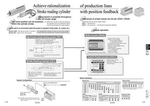
Achieve rationalization Stroke reading cylinder Measurement is possible throughout the full stroke range. When the counter is reset by pressing The home position can be anywhere the cylinder rod to the reference plane, within the cylinder stroke. that point becomes the home position. that point becomes the home position. of production lines with position feedback Tolerances of preset values can be set. (CEU1, CEU5) Tolerances can be set for preset values. CEU1: ± set tolerance CEU5: + set tolerance, – set tolerance (separate settings) Can be used in an environment where the product is exposed...
Open the catalog to page 2
Application Examples Parts inspection parts, discriminates between good and defective articles, hydraulic cylinder by detecting its Even if the size of the workpiece changes, the point of press-in completion can be easily changed. deceleration point Since the deceleration point of the die easily changed after replacement of Length/breadth discrimination Distinguishes either lengthwise or crosswise while correcting the Maintains a constant height of I measuring workpiece height. ! Detection of lifter position lifter's stroke. I Inspection of machined holes Can detect machined hole depth, burrs...
Open the catalog to page 3
Stroke Reading Cylinder Series Measurement Principle The amount of rod movement in the stroke reading cylinder is detected using an MR element (magnetic resistance element) whose resistance value changes due to magnetic force. The detection unit containing this MR element is called the sensor head. An amplifying circuit and a dividing circuit are required to produce output which can be read by the counter, and these are attached to the cylinder case. The sensor head and amplifier section together are referred to as the sensor unit. Sensor head Cylinder unit The stroke reading cylinder is equipped...
Open the catalog to page 4
Specific Product Precautions Be sure to read before handling. Refer to front matters 42 and 43 for Safety Instructions and pages 3 to 11 for Actuator and Auto Switch Precautions. 1. When screwing a nut or fitting, etc. onto the threaded section at the end of the piston rod, return the piston rod to its fully retracted position, and grasp the exposed portion of the rod across two parallel sides with a wrench. In the case of the high precision stroke reading cylinder, there are no parallel sides. Secure the workpiece with a double nut. Note) Do not apply rotational torque to the piston rod. 2....
Open the catalog to page 5
High Precision Stroke Reading Cylinder Non-rotating Piston Type Note) CE compliant: When connecting power supply voltage 24 VDC) operation manual for details. High precision stroke reading cylinder Mounting style Bore size Standard cylinder stroke (mm) Refer to "Standard Stroke" on page 1445. Referto page 1445 for details. Number of auto switches Auto switch Nil I Without auto switch (Built-in magnet) For the applicable auto switch model, refer to Sensor cable length Applicable counter Mounting Bracket Part No. Cable length Applicable AutO Switch/Refer to pages 1719 to I827 for further information...
Open the catalog to page 7
High Precision Stroke Reading Cylinder Non-rotating Piston Type SOflOS Cylinder Specifications Made to Order Specifications (For details, refer to page 1918.) Fluororubber seals Sensor Specifications Note 1) This includes the digital display error of the counter (CEU5). When strokes are over 100 mm, accuracy is ±0.05 mm. Moreover, the overall accuracy after mounting on equipment will vary depending on mounting conditions and the environment. Therefore, the customer should calibrate the Note 2) Except for the connector, the cylinder section is the equivalent of an SMC water resistant Cylinder...
Open the catalog to page 8
Mass (Without mounting bracket/connector)_ Auto Switch Proper Mounting Position Regarding dimensions for the auto switch proper mounting position (at stroke end), refer to page 1452. Electrical Wiring Output type The output signal of the high precision stroke reading cylinder is A/B phase difference output (open collector output) as shown in the figure below. The relation between the movement distance and the signal output of the high precision stroke reading cylinder is that for each 0.04 mm of movement a one pulse signal is output to both output terminals A and B. In order to measure with a...
Open the catalog to page 9
High Precision Stroke Reading Cylinder Non-rotating Piston Type Series Component Parts Component Parts * Since there is a possibility of improper operation, please contact SMC regarding the replacement of seals.
Open the catalog to page 10
Direct mounting, rod side tapped style: Metal connector Width across flats 8 4 X M5 X 0.8 depth 6 (Bottom 04.3 through-hole)
Open the catalog to page 11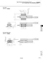
High Precision Stroke Reading Cylinder Non-rotating Piston Type Series Foot style: Rod side flange style:
Open the catalog to page 12
Auto Switch Proper Mounting Position (Detection at Stroke End) Operating Range Auto switch Note) Adjust the auto switch after confirming the operating conditions in the actual setting. ► Since the operating range is provided as a guideline including hysteresis, it cannot be guaranteed (assuming approximately ±30% dispersion). It may vary substantially depending on an ambient Other than the models listed in "How to Order", the following auto switches are applicable. * For solid state auto switches, auto switches with a pre-wired connector are also available. Referto pages 1784 and 1785 * Normally...
Open the catalog to page 15
Stroke Reading Cylinder Note) CE compliant: When connecting Refer to the counter operation Mounting style* Bore size Cable length •Auto switch auto switches Without auto switch (Built-in magnet) switch model, refer to Standard cylinder stroke (mm) Refer to "Standard Stroke" on page 1455 (Applicable bore size 040 to 063) Applicable counter Cable length * 012, 020, 032: Without cushion only. Applicable AutO Switch/Refer to pages 1719 to I827 for further information on auto switches. ** Water resistant type auto switches can be mounted on the above models, but in such case SMC cannot guarantee water...
Open the catalog to page 17All SMC catalogs and technical brochures
 In-line Type Vacuum Ejector
6 Pages
 Serie HRR
64 Pages
 Série VP/VG
33 Pages
 Série XL
27 Pages
 Série ACG/ARG/AWG
45 Pages
 Série JXC5H/6H
36 Pages
 LEJS100-X400 series
15 Pages
 JMB series
13 Pages
 JCM series
21 Pages
 PF3A7*H
40 Pages
 PF3W
PF3W34 Pages
 Compact Guide Cylinder with Lock
36 Pages
 Water Treatment
16 Pages
 Food & Packaging Industry
4 Pages
 Digital Gap Checker
26 Pages
 Vacuum Pad
16 Pages
 One-touch Fittings
224 Pages
 Soft Start-up Valve
16 Pages
 Electric Actuator
272 Pages
 Rotary Actuator
40 Pages
 Compact Guide Cylinder
18 Pages
 Compact Slide
24 Pages
 Air Cylinder
124 Pages
 LEFB, LEFG-BS series
180 Pages
 JMGP series
16 Pages
 ISO Cylinder
32 Pages
 IZD10
IZD1020 Pages
 IZH10
IZH108 Pages
 Fan Type Lonizer
28 Pages
 Check Valves
4 Pages
 Compact Cylinder/Clean series
16 Pages
 3 port solenoid Valve
74 Pages
 Vacuum Ejector Series ZM
20 Pages
 Series ZL
20 Pages
 Series CM2
92 Pages
 Series IDGA/IDG
56 Pages
 Platform Cylinder Series CXT
14 Pages
 IDH-A
IDH-A12 Pages
 CP96-C96-B
74 Pages
 CVQ
CVQ24 Pages
 HY
HY52 Pages
 VNA
VNA10 Pages
 Series MXY
28 Pages
 Series MXP
39 Pages
 Air Slide Table
132 Pages
 Compact Cylinder Series CQ2
138 Pages
 S0700
S0700112 Pages
 SYJ
SYJ96 Pages
 SY - NEW
164 Pages
 VF
VF60 Pages
 C(D)55 series
24 Pages
 C(D)Q2 series
216 Pages
 MGP series
36 Pages
 11-LEFS series
19 Pages
 LECS series
16 Pages
 LECPA series
4 Pages
 KQ series
80 Pages
 IDF series
16 Pages
 ZP series
69 Pages
 MHF series
32 Pages
 MHZ series
68 Pages
 CRB series
44 Pages
 MGJ series
7 Pages
 AC series
98 Pages
 VH series
14 Pages
 LVA series
43 Pages
 VDW series
28 Pages
 LVM series
28 Pages
 VX2 series
32 Pages
 MXH series
32 Pages
 MXF series
12 Pages
 CXW series
48 Pages
 CXS series
76 Pages
 CQS series
40 Pages
 CQM series
28 Pages
 CLQ series
36 Pages


