- Products
- Catalogs
- News & Trends
- Exhibitions
C(D)55 series
1 /24Pages

C(D)55 series
1 /24Pages
Catalog excerpts

Compact Cylinder ISO Standards [ISO/21287] It is possible to mount small auto switches on 4 surfaces. Auto switches can be mounted on any of the 4 surfaces, depending on the installation conditions. Improved flexibility of system design. 2-colour indication solid state auto switch Appropriate setting of the mounting position can be performed without mistakes. Operating range Proper operating range light lights up at a proper operating range. Even if 2-colour indication solid state auto switches are fixed at a proper operating range (the green light lights up), the operation may become unstable depending on the installation environment or magnetic field disturbance. (Magnetic body, external magnetic field, proximal installation of cylinders with built-in magnet and actuators, temperature change, other factors for magnetic force fluctuation during operation, etc.)
Open the catalog to page 1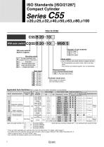
ISO Standards [ISO/21287] Compact Cylinder C55 B 20 10 With auto switch M9B S Number of auto switches With auto switch (Built-in magnet) Through-hole/Both ends tapped common (Standard) Foot style Rod side flange style Head side flange style Single clevis style Auto switch — Without auto switch (Built-in magnet cylinder) ∗ For the applicable auto switch model, refer to the table below. ∗ Auto switches are shipped together, (but not assembled). Bore size Rod end female thread Rod end male thread Cylinder stroke (mm) Refer to page 2 for standard and intermediate strokes. Special function Electrical...
Open the catalog to page 2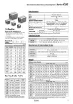
ISO Standards [ISO/21287] Compact Cylinder Specifications Type Action Fluid Proof pressure Maximum operating pressure Minimum operating pressure Pneumatic (Non-lube) Double acting, Single rod Air 1.5 MPa 1.0 MPa 0.05 MPa (ø20 to ø63), 0.03 MPa (ø80, ø100) Without auto switch: –10 to 70°C (No freezing) With auto switch: –10 to 60°C (No freezing) Rubber bumper on both end +1.0 0 mm Through-hole/Both ends tapped common 50 to 500 mm/s 50 to 300 mm/s Ambient and fluid temperature Cushion Stroke length tolerance Note) Be sure to read before handling. qRefer to back cover for Safety Instructions and...
Open the catalog to page 3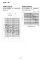
Series C55 Allowable Lateral Load Allowable Kinetic Energy Make sure to operate strictly within the allowable lateral load range to the rod end. Make sure to operate strictly within the allowable range of the load weight and maximum speed. Operation outside of this range may result in shorter service life or damage to the device. Operation outside of this range may cause excessive impact, which may result in damage to the device. Operating pressure: 1 MPa Allowable lateral load (N) Stroke + Eccentric distance (mm) ∗ Refer to Model Selection in Best Pneumatics No.2 for details about model selection...
Open the catalog to page 4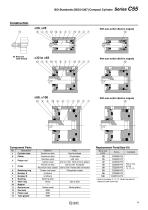
ISO Standards [ISO/21287] Compact Cylinder With auto switch (Built-in magnet) With auto switch (Built-in magnet) With auto switch (Built-in magnet) Description Cylinder tube Piston Retaining ring Bumper A Bumper B Bushing Wear ring Magnet Rod end nut Rod seal Piston seal Tube gasket Replacement Parts/Seal Kit Material Aluminum alloy Aluminum alloy Stainless steel Carbon steel Aluminum alloy Aluminum alloy casted Carbon tool steel Urethane Urethane Bearing alloy Resin — Carbon steel NBR NBR NBR Note Hard anodised Chromated ø20, ø25 ø32 to ø100 Hard chrome plated ø20 to ø40 Anodized ø50 to ø100...
Open the catalog to page 5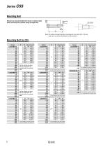
Series C55 Mounting Bolt Should use recommended bolt shown as below table when mounting the cylinder using through-hole. Mounting bolt Note) To install a through-hole type mounting bolt, bore size 20 to 100 mm, make sure to use the flat washer that is provided. Fix the cylinder by using the OA thread that are provided with the cylinder tube. Fix the cylinder by using the OA thread that are provided with the cylinder tube. Fix the cylinder by using the OA thread that are provided with the cylinder tube. Fix the cylinder by using the OA thread that are provided with the cylinder tube. Fix the cylinder...
Open the catalog to page 6
ISO Standards [ISO/21287] Compact Cylinder Series C55 [First angle projection] ø20, ø25 øN through (4 positions) (The same four-place size) H thread effective depth C OA (4 positions) (The same four-place size) øOB counterbore RB (4 positions) (The same four-place size) Auto switch M5 x 0.8 (2 positions) Port size Width across flats K Hexagon width across flats B1 Rod end nut Basic Style
Open the catalog to page 7
[First angle projection] OA (4 positions) (The same four-place size) 2 x 4 x RA L H thread effective depth C øN through (4 positions) (The same four-place size) øOB counterbore RB (4 positions) (The same four-place size) Auto switch G1/8 (2 positions) Port size Width across flats K Hexagon width across flats B1 Rod end nut Basic Style
Open the catalog to page 8
ISO Standards [ISO/21287] Compact Cylinder Series C55 [First angle projection] ø80, ø100 M12 x 1.75 effective depth 21 Auto switch M10 x 1.5 effective depth 15 (4 positions) (The same four-place size) B + Stroke ø8.4 through (4 positions) (The same four-place size) E ø13.5 counterbore 5 (4 positions) (The same four-place size) M: Rod end male thread Width across flats K Hexagon width across flats 24 Basic Style Bore size (mm) Rod End Male Thread (mm) Bore size (mm)
Open the catalog to page 9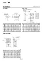
Series C55 Mounting Bracket [First angle projection] Flange bracket Foot bracket Hexagon socket head cap screw (Accessory) FL 4 x øFD Hexagon socket head cap screw (Accessory) Hexagon socket head cap screw Single clevis bracket Hexagon socket head cap screw (Accessory) Hexagon socket head cap screw Hexagon socket head cap screw
Open the catalog to page 10
ISO Standards [ISO/21287] Compact Cylinder Proper Auto Switch Mounting Position (Detection at Stroke End) and Its Mounting Height Reed auto switch Solid state auto switch Series C55 [First angle projection] ∗ Figures in the table below are used as a reference when mounting the auto switches for stroke end detection. In the case of actually setting the auto switches, adjust them after confirming their operation. (mm) Negative figures in the table W indicate an auto switch is mounted outward from the edge of the cylinder body. Reed auto switch Solid state auto switch ∗ Figures in the table below...
Open the catalog to page 11All SMC catalogs and technical brochures
 In-line Type Vacuum Ejector
6 Pages
 Serie HRR
64 Pages
 Série VP/VG
33 Pages
 Série XL
27 Pages
 Série ACG/ARG/AWG
45 Pages
 Série JXC5H/6H
36 Pages
 LEJS100-X400 series
15 Pages
 JMB series
13 Pages
 JCM series
21 Pages
 PF3A7*H
40 Pages
 PF3W
PF3W34 Pages
 Compact Guide Cylinder with Lock
36 Pages
 Water Treatment
16 Pages
 Food & Packaging Industry
4 Pages
 Digital Gap Checker
26 Pages
 Vacuum Pad
16 Pages
 One-touch Fittings
224 Pages
 Soft Start-up Valve
16 Pages
 Electric Actuator
272 Pages
 Rotary Actuator
40 Pages
 Compact Guide Cylinder
18 Pages
 Compact Slide
24 Pages
 Air Cylinder
124 Pages
 LEFB, LEFG-BS series
180 Pages
 JMGP series
16 Pages
 ISO Cylinder
32 Pages
 IZD10
IZD1020 Pages
 IZH10
IZH108 Pages
 Fan Type Lonizer
28 Pages
 Check Valves
4 Pages
 Compact Cylinder/Clean series
16 Pages
 3 port solenoid Valve
74 Pages
 Vacuum Ejector Series ZM
20 Pages
 Series ZL
20 Pages
 Series CM2
92 Pages
 Series IDGA/IDG
56 Pages
 Platform Cylinder Series CXT
14 Pages
 IDH-A
IDH-A12 Pages
 CP96-C96-B
74 Pages
 CVQ
CVQ24 Pages
 HY
HY52 Pages
 VNA
VNA10 Pages
 Series MXY
28 Pages
 Series MXP
39 Pages
 Air Slide Table
132 Pages
 Compact Cylinder Series CQ2
138 Pages
 S0700
S0700112 Pages
 SYJ
SYJ96 Pages
 SY - NEW
164 Pages
 VF
VF60 Pages
 C(D)Q2 series
216 Pages
 MGP series
36 Pages
 11-LEFS series
19 Pages
 LECS series
16 Pages
 LECPA series
4 Pages
 KQ series
80 Pages
 IDF series
16 Pages
 ZP series
69 Pages
 MHF series
32 Pages
 MHZ series
68 Pages
 CRB series
44 Pages
 MGJ series
7 Pages
 AC series
98 Pages
 VH series
14 Pages
 LVA series
43 Pages
 VDW series
28 Pages
 LVM series
28 Pages
 VX2 series
32 Pages
 MXH series
32 Pages
 MXF series
12 Pages
 CXW series
48 Pages
 CXS series
76 Pages
 CQS series
40 Pages
 CQM series
28 Pages
 CLQ series
36 Pages


