- Products
- Catalogs
- News & Trends
- Exhibitions
11-LEFS series
1 /19Pages

11-LEFS series
1 /19Pages
Catalog excerpts

Electric Actuator/Slider Type ©2012 SMC Corporation All Rights Reserved (Clean Room Specification) [Clean Room Specification ] ISO Class 4 (Class 10)! • Built-in vacuum piping • Possible to mount the main body without removing the external cover, • Body-integrated linear guide Vacuum exhaust minimises external particle generation from the ball screw Step Motor (Servo/24 VDC) T Servo Motor (24VDC) Ball Screw Drive Series 11-LEFS AC Servo Motor (100/200/400 W) Type Ball Screw Drive Series 11-LEFS • High output motor (100/200/400 W) • Improved high speed transfer ability (Max.: 1,000 m/s) • High acceleration compatible (5,000 mm/s2) • Pulse input type/CC-Link direct input type/SSCNET III type • With internal absolute encoder (LECSB specification)
Open the catalog to page 1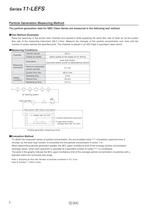
Particle Generation Measuring Method_ The particle generation data for SMC Clean Series are measured in the following test method. ■Test Method (Example) Place the specimen in the acrylic resin chamber and operate it while supplying the same flow rate of clean air as the suction flow rate of the measuring instrument (28.3 L/min). Measure the changes of the particle concentration over time until the number of cycles reaches the specified point. The chamber is placed in an ISO Class 5 equivalent clean bench. ■Measuring Conditions - Clean bench (ISO Class 5 equivalent) ■ -|> Supply rate 15 L/min...
Open the catalog to page 2
Electric Actuator/Slider Type Series 7 l-Lcro Particle Generation Characteristics Step Motor (Servo/24 VDC), Servo Motor (24 VDC)
Open the catalog to page 3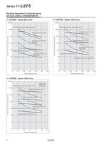
Particle Generation Characteristics ISO Class 6 (Class 1000) upper limit upper limit Suction flow rate: 0 L/min Suction flow rate: 50 L/min" Suction flow rate: 80 L/min'-^k^iPP^ limit- Suction flow rate: 100 L/min
Open the catalog to page 4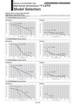
Electric Actuator/Slider Type Ball Screw Drive/Ser/es 11-LEFS Model Selection Speed-Work Load Graph (Guide) : The following graph shows the values when positioning force is 100%.
Open the catalog to page 5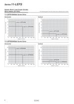
Speed-Work Load Graph (Guide) : The following graph shows the values when positioning force is 250%.
Open the catalog to page 6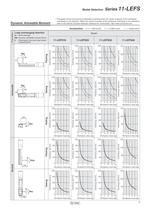
Model Selection Series 7 l-Lcro Dynamic Allowable Moment This graph shows the amount of allowable overhang when the centre of gravity of the workpiece overhangs in one direction. When the centre of gravity of the workpiece overhangs in two directions, refer to the Electric Actuator Selection Software for confirmation, http://www.smcworld.com Load overhanging direction Me: Dynamic allowable moment [N-m] L : Overhang to the work load centre
Open the catalog to page 7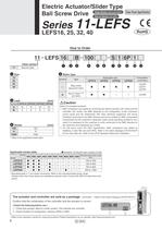
Electric Actuator/Slider Type_ Ball Screw Drive *8i™B"8" (Clean Room Specification] Clean series Vacuum type * Refer to the applicable stroke table. Applicable stroke table Note) CE-compliant products © EMC compliance was tested by combining the electric actuator LEF series and the controller LEC series. The EMC depends on the configuration of the customer's control panel and the relationship with other electrical equipment and wiring. Therefore conformity to the EMC directive cannot be certified for SMC components incorporated into the customer's equipment under actual operating conditions....
Open the catalog to page 8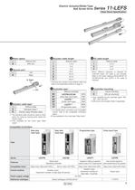
Electric Actuator/Slider Type . -f-f | rro Ball Screw Drive Series 7 I'LCrO [Clean Room Specification] ©Motor option ©Actuator cable type* *1 The standard cable should be used on fixed parts. For using on moving parts, select the robotic cable. *2 Only available for the motor type "Step ©Actuator cable length * Produced upon receipt of order (Robotic cable Refer to the specifications Note 2) on page 10 ©Controller type* *1 For details about controllers and compatible motors, refer to the compatible controllers *2 Only available for the motor type "Step motor" * When "Without controller" is selected...
Open the catalog to page 9
[Clean Room Specification] Note 1) Strokes shown in () are produced upon receipt of order. Note 2) Speed is changed by the work load. Check "Speed-Work Load Graph (Guide)" on page 5. Furthermore, if the cable length exceeds 5 m, then it will Note 3) Impact resistance: No malfunction occurred when the actuator was tested with a drop tester in both an axial direction and a perpendicular direction to the lead screw. (Test was performed with the actuator in the initial state.) Vibration resistance: No malfunction occurred in a test ranging between 45 to 2000 Hz. Test was performed in both an axial...
Open the catalog to page 10
Electric Actuator/Slider Type . -4-4 I rro Ball Screw Drive Series 7 I'LCrO [Clean Room Specification ] Note 1) Strokes shown in () are produced upon receipt of order. Note 2) Check "Speed-Work Load Graph (Guide)" on page 6. Furthermore, if the cable length exceeds 5 m, then it will decrease by up to 10% for each 5 m. Note 3) Impact resistance: No malfunction occurred when the actuator was tested with a drop tester in both an axial direction and a perpendicular direction to the lead screw. (Test was performed with the actuator in the initial state.) Vibration resistance: No malfunction occurred...
Open the catalog to page 11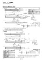
Series 11-LEFS Clean Room Specification Dimensions: Ball Screw Drive 3H9 ( 0 depth 3 +0.025 ) [mm] Model 11-LEFS16२-100 11-LEFS16२-100B 11-LEFS16२-200 11-LEFS16२-200B 11-LEFS16२-300 11-LEFS16२-300B 11-LEFS16२-400 11-LEFS16२-400B 65 34 4 n x ø3.4 100 8 D x 100 (=E) B Cable length ≈ 250 (L) A (Table traveling distance) Note 2) 37 39[(41)] 2[4] Stroke Origin Note 3) (2.4) 65 40 n D E 106 180 4 — — 206 280 6 2 200 306 380 8 3 300 406 480 10 4 400 40 27 20 Vacuum port M5 x 0.5 x 5 5.5 (72) 40 24 M4 x 0.7 thread depth 7 (F.G. terminal) 28 33 Body mounting reference plane Note 1) B Motor cable (2 x...
Open the catalog to page 12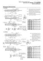
Electric Actuator/Slider Type Ball Screw Drive Series 11-LEFS Clean Room Specification Dimensions: Ball Screw Drive 11-LEFS32 +0.030 5H9 ( 0 depth 5 ) Note 1) When mounting the electric actuator using the body mounting reference plane, set the height of the opposite surface or pin to 3 mm or more because of R chamfering. (Recommended height: 5 mm) Note 2) Distance within which the table can move when it returns to origin. Make sure a workpiece mounted on the table does not interfere with the workpieces and facilities around the table. Note 3) Position after return to origin. Note 4) The number...
Open the catalog to page 13All SMC catalogs and technical brochures
 In-line Type Vacuum Ejector
6 Pages
 Serie HRR
64 Pages
 Série VP/VG
33 Pages
 Série XL
27 Pages
 Série ACG/ARG/AWG
45 Pages
 Série JXC5H/6H
36 Pages
 LEJS100-X400 series
15 Pages
 JMB series
13 Pages
 JCM series
21 Pages
 PF3A7*H
40 Pages
 PF3W
PF3W34 Pages
 Compact Guide Cylinder with Lock
36 Pages
 Water Treatment
16 Pages
 Food & Packaging Industry
4 Pages
 Digital Gap Checker
26 Pages
 Vacuum Pad
16 Pages
 One-touch Fittings
224 Pages
 Soft Start-up Valve
16 Pages
 Electric Actuator
272 Pages
 Rotary Actuator
40 Pages
 Compact Guide Cylinder
18 Pages
 Compact Slide
24 Pages
 Air Cylinder
124 Pages
 LEFB, LEFG-BS series
180 Pages
 JMGP series
16 Pages
 ISO Cylinder
32 Pages
 IZD10
IZD1020 Pages
 IZH10
IZH108 Pages
 Fan Type Lonizer
28 Pages
 Check Valves
4 Pages
 Compact Cylinder/Clean series
16 Pages
 3 port solenoid Valve
74 Pages
 Vacuum Ejector Series ZM
20 Pages
 Series ZL
20 Pages
 Series CM2
92 Pages
 Series IDGA/IDG
56 Pages
 Platform Cylinder Series CXT
14 Pages
 IDH-A
IDH-A12 Pages
 CP96-C96-B
74 Pages
 CVQ
CVQ24 Pages
 HY
HY52 Pages
 VNA
VNA10 Pages
 Series MXY
28 Pages
 Series MXP
39 Pages
 Air Slide Table
132 Pages
 Compact Cylinder Series CQ2
138 Pages
 S0700
S0700112 Pages
 SYJ
SYJ96 Pages
 SY - NEW
164 Pages
 VF
VF60 Pages
 C(D)55 series
24 Pages
 C(D)Q2 series
216 Pages
 MGP series
36 Pages
 LECS series
16 Pages
 LECPA series
4 Pages
 KQ series
80 Pages
 IDF series
16 Pages
 ZP series
69 Pages
 MHF series
32 Pages
 MHZ series
68 Pages
 CRB series
44 Pages
 MGJ series
7 Pages
 AC series
98 Pages
 VH series
14 Pages
 LVA series
43 Pages
 VDW series
28 Pages
 LVM series
28 Pages
 VX2 series
32 Pages
 MXH series
32 Pages
 MXF series
12 Pages
 CXW series
48 Pages
 CXS series
76 Pages
 CQS series
40 Pages
 CQM series
28 Pages
 CLQ series
36 Pages


