- Catalogs
- SMC PNEUMATIC
- Series MB
Series MB
1 /24Pages

Series MB
1 /24Pages
Catalog excerpts
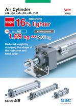
Air Cylinder ø32, ø40, ø50, ø63, ø80, ø100 New RoHS 16% lighter (ø63-100 stroke) Weight New Series MB 1.69 kg Existing model 2.01 kg Reduced weight by changing the shape of the rod cover and head cover. Series MB CAT.ES20-231A
Open the catalog to page 1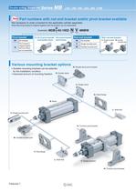
Double acting, Single rod New Series MB ø32, ø40, ø50, ø63, ø80, ø100 Part numbers with rod end bracket and/or pivot bracket available Not necessary to order a bracket for the applicable cylinder separately Note) Mounting bracket is shipped together with the product, but not assembled. Example) Pivot bracket Nil No bracket N D MDB T 40-100Z- N N: Kit of pivot bracket Kit of pivot bracket and double clevis and trunnion Pivot bracket is shipped together with the product, but not assembled. V -M9BW Rod end bracket With rod end bracket Single knuckle joint W • Suitable mounting brackets can be selected...
Open the catalog to page 2
Air Cylinder Lightweight Applicable speed/load Piston speed: Max. 1000 mm/s (ø32 to ø100) Load yield: See table below. Reduced weight by changing the shape of the rod cover and head cover. (kg) (kg) Bore size (mm) New MB 32 0.59 18% 0.72 32 80 40 0.84 17% 1.01 40 140 50 1.43 16% 1.71 50 190 63 1.69 16% 2.01 63 310 80 2.95 17% 3.57 80 500 100 4.18 13% 4.82 100 800 Reduction rate Existing model Bore size (mm) Maximum load mass Port Speed: 200 mm/s Various switches such as compact auto switches and magnetic field resistant auto switches can be mounted. Mounting dimensions are the same as the existing...
Open the catalog to page 3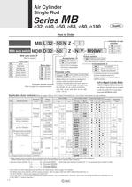
Air Cylinder Single Rod Series MB ø32, ø40, ø50, ø63, ø80, ø100 RoHS How to Order Number of auto switches MB L 32 50 N Z With auto switch With auto switch Accessories 1 (Built-in magnet) Nil No bracket N Pivot bracket ∗ Only for D and T mounting types. ∗ Pivot bracket is shipped together with the product. Mounting B L F G C D T Z N V M9BW MDB D 32 50 Basic Axial foot Rod flange Head flange Single clevis Double clevis Center trunnion Bore size 32 32 mm 40 40 mm 50 50 mm 63 63 mm 80 80 mm 100 100 mm Cylinder stroke (mm) Refer to page 2 for standard strokes. Nil N∗ 2 pcs. 1 pc. 3 pcs. “n” pcs. Auto...
Open the catalog to page 4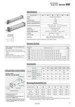
Double acting Refer to pages 11 to 16 for cylinders with auto switches • Auto switch proper mounting position (detection at stroke end) and its mounting • Operating range • Minimum stroke for auto switch mounting • Auto switch mounting brackets/Part no. Note) Model without air cushion is designed to include rubber bumpers. Standard Strokes Manufacture of intermidiate strokes is possible. (Spacers are not used.) Produced upon receipt of order. Ordering Example of Cylinder Assembly Cylinder model: Double clevis ^Double knuckle joint Mounting D: Double clevis Rod end bracket W: Double knuckle joint...
Open the catalog to page 5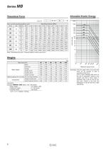
Theoretical Force Allowable Kinetic Energy Note) Theoretical force (N) = Pressure (MPa) x Piston area (mm2) Example) MBB32-100Z (Basic, 032, 100 stroke) (Example) Find the upper limit of rod end load From a point indicating 500 mm/s on the axis of abscissas, extend a line upward and find a point where it intersects with a line for the 63 mm bore size. Extend a line from the intersection to the left and find a load
Open the catalog to page 6
Air Cylinder Single Rod Series MB Construction @0 !4 i q !2 !6 !1 e r !9 y !5 @1 !3 t !8 u w o !0 !7 Component Parts No. 1 2 3 4 5 6 7 8 9 10 11 12 13 14 15 16 17 18 19 20 21 Description Rod cover Head cover Cylinder tube Piston rod Piston Cushion ring Cushion ring B Bushing Cushion valve Retaining ring Tie rod Tie rod nut Wear ring Rod seal Piston seal Cushion seal Cushion valve seal Cylinder tube gasket Piston gasket Rod end nut Magnet Material Aluminum die-cast Aluminum die-cast Aluminum alloy Carbon steel Aluminum alloy Aluminum alloy Aluminum alloy Bearing alloy Steel wire Steel for spring...
Open the catalog to page 7
Air Cylinder Single Rod Standard/With Mounting Bracket Series MB Refer to Basic (B) for other dimensions. Axial foot/(MBL) Port LY Cushion valve LT X X Y (mm) Stroke range 32 40 LD LH LS LX LZ Y LS + Stroke ZZ + Stroke Axial Foot Bore size (mm) LH 4 x øLD LZ X Y ZZ Without Air Cushion Bore size (mm) LT LX LY Up to 700 7 30 128 3.2 32 53 50 22 9 162 32 134 168 Up to 800 9 33 132 3.2 38 59 55 24 11 170 40 138 176 50 Up to 1000 9 40 148 3.2 46 72.5 70 27 11 190 50 156 198 63 Up to 1000 12 45 148 3.6 56 82.5 80 27 14 193 63 156 201 80 Up to 1000 12 55 174 4.5 72 102.5 100 30 14 230 80 184 240 100...
Open the catalog to page 9
Series MB Standard/With Mounting Bracket Refer to Basic (B) for other dimensions. Head flange/(MBG) Port 4 x øFD FY FB Cushion valve FT FX FZ ZZ + Stroke Head Flange Without Air Cushion (mm) Bore size (mm) Stroke range 32 Up to 700 50 7 10 64 32 40 Up to 800 55 9 10 72 36 50 Up to 1000 70 9 12 63 Up to 1000 80 Bore size (mm) ZZ 79 141 32 147 90 145 40 151 90 45 110 164 50 172 9 12 100 50 120 164 63 172 80 Up to 1000 100 12 16 126 63 153 202 80 212 100 Up to 1000 120 14 16 150 75 178 202 100 212 FB FD FT FX FY FZ ZZ Model without air cushion is designed to include rubber bumpers. Since the bumpers...
Open the catalog to page 10
Air Cylinder Single Rod Standard/With Mounting Bracket Series MB Refer to Basic (B) for other dimensions. Double clevis/(MBD) Port Cushion valve Hole dia.: CDH10 Shaft dia.: CDd9 U CX CZ L Z + Stroke ZZ + Stroke RR Double Clevis Bore size (mm) (mm) Stroke range CDH10 CDd9 CX CZ L RR U Z ZZ Without Air Cushion Bore size (mm) Z ZZ 32 Up to 700 10+0.058 0 10−0.040 −0.076 14+0.3 +0.1 28 23 10.5 13 154 164.5 32 160 170.5 40 Up to 800 10+0.058 0 10−0.040 −0.076 14+0.3 +0.1 28 23 11 13 158 169 40 164 175 50 Up to 1000 14+0.070 0 14−0.050 −0.093 20+0.3 +0.1 40 30 15 17 182 197 50 190 205 63 Up to 1000...
Open the catalog to page 11
Series MB Auto Switch Mounting Auto Switch Proper Mounting Position (Detection at stroke end) and Its Mounting Height D-A3 /G39/K39 D-M9 D-M9 D-M9 D-A9 /M9 V W/M9 WV A/M9 AV /A9 V Hs Hs Auto switch A Ht Ht Auto switch D-Z7 /Z80 D-Y59 /Y69 /Y7P/Y7PV D-Y7 W/Y7 WV/Y7BA B A D-A44 B D-A5 /A6 D-A59W Hs Hs Auto switch A Ht Ht Auto switch A B B D-F5 /J5 D-F5 W/J59W/F5BA D-F59F/F5NT Hs Ht Auto switch A B D-P3DW Hs Ht Auto switch A B D-P4DW Hs Ht Auto switch A 11 B
Open the catalog to page 14All SMC PNEUMATIC catalogs and technical brochures
 Vacuum Unit 2024
99 Pages
 Air Cylinder CJ2 Series
117 Pages
 AS-FS Series
36 Pages
 IDF series
12 Pages
 MHL2 Series
24 Pages
 JCM Serie
18 Pages
 EX245 Series
12 Pages
 Pin Cylinder CJP2/CDJP2/CJP
19 Pages
 5 Port Solenoid Valve VQC
63 Pages
 5 Port Solenoid Valve VQ
79 Pages
 SY
SY268 Pages
 5-p0979-0980-hep500
2 Pages
 5-p0977-0978-aep100
2 Pages
 5-p0966-0971-lmu
5 Pages
 5-p0960-0966-alb900
6 Pages
 5-p0956-0960-ald600
5 Pages
 5-p0948-0950-al800
3 Pages
 es70-44c-vx2
52 Pages
 es50-37-kq2
124 Pages
 ex-pcw
23 Pages
 1-p2124-2152-ex510
29 Pages
 1-p2111-2122-ex500
12 Pages
 1-p2063-2073-ex260
11 Pages
 4-p0147-0178-msu-mds
32 Pages
 es20-230b-crb2
59 Pages
 1-p1869-1878-vp3145
10 Pages
 VP300/500/700 series
42 Pages
 1-p1789-1829-vqz100
41 Pages
 1-p1727-1788-syj300
62 Pages
 5 Port Solenoid Valve S0700
111 Pages
 5 Port Solenoid Valve VF
59 Pages
 5 Port Solenoid Valve SV
127 Pages
 VH
VH9 Pages
 CUJ
CUJ41 Pages
 AL
AL3 Pages
 kj mm
kj mm9 Pages
 AQ
AQ4 Pages
 SY3000/5000-X13
2 Pages
 Series LES
23 Pages
 Series LEFB
16 Pages
 Series PF3W
28 Pages
 Series IDG?A/IDG
56 Pages
 Floating Joint
7 Pages
 Series IZS40/41/42
32 Pages
 Series LEY
7 Pages
 Series VHS
12 Pages
 Series CY1S
28 Pages
 SeriesCQ2/CQS/CQ
4 Pages
 In-line Air Filter
12 Pages
 5 Port Solenoid Valve
60 Pages
 Series CQ2/CQS
2 Pages
 AS series
2 Pages
 corporate guide
13 Pages
 ZP
ZP69 Pages
 ZFA
ZFA14 Pages
 ZA
ZA13 Pages
 MHF
MHF32 Pages
 MHZ
MHZ68 Pages
 CRB
CRB44 Pages
 D
D117 Pages
 RB
RB23 Pages
 CEP
CEP44 Pages
 RSK
RSK30 Pages
 CLK
CLK51 Pages
 MK
MK20 Pages
 GLJ
GLJ65 Pages
 MGJ
MGJ7 Pages
 Mx
Mx36 Pages
 MXH
MXH18 Pages
 My3
My356 Pages
 my1b
my1b20 Pages
 CC
CC15 Pages
 J
J14 Pages
 CQ2
CQ251 Pages
 standard cylinder
84 Pages
 VFN
VFN6 Pages
 SY3000
246 Pages
 SJ3A6
SJ3A618 Pages
 1301/IW
14 Pages
 CHQ/CHDQ
19 Pages
 AC
AC95 Pages
 HAW
HAW4 Pages
 HAA
HAA3 Pages
 ZB
ZB24 Pages
 CRB2
CRB235 Pages


Archived catalogs
 CJ1
CJ15 Pages
 SYJ
SYJ62 Pages
 SJ
SJ78 Pages
 Vacuum Unit ZK2 Series
60 Pages
 SYJ300/500/700 Series
62 Pages
