- Catalogs
- SMC PNEUMATIC
- Series CY1S
Series CY1S
1 /28Pages

Series CY1S
1 /28Pages
Catalog excerpts

Magnetically Coupled Rodless Cylinder New ø6, ø10, ø15, ø20, ø25, ø32, ø40 Weight 15 % reduced RoHS Overall length 15 mm shortened Max. Max. 0.96 kg (Existing model 1.13 kg) 240 mm (Existing model 255 mm) (CY1S 15-100 stroke) (CY1S 40-100 stroke) Reduced in length Improved durability Lub-retainers are mounted on the internal and external surfaces of the cylinder tube to maintain the lubrication. External surface lub-retainers Cylinder tube Adjustment bolt improves stroke accuracy/repeatability. Stroke position can be maintained with the adjustment bolt positioned next to the shock absorber, so stroke adjustment is not necessary. Adjustment bolt Internal surface lub-retainers Series CY1S Shock absorber CAT.ES20-227A
Open the catalog to page 1
Series CY1S Reduced in weight Weight is reduced with the redesign of the slide block and reducing the thickness of the plate. Bore size (mm) (kg) Reduction rate Existing model New CY1S 6 0.34 8% 0.37 10 0.59 13% 0.68 15 0.96 15% 1.13 20 1.68 13% 1.93 25 2.02 10% 2.25 32 3.45 12% 3.94 40 5.36 14% 6.23 Slide block At 100 stroke Plate Reduced in length Overall length is reduced, but interchangeable with the existing model. (mm) Bore size (mm) New CY1S Existing Bilateral piping type Centralized piping type model Overall length Length reduction Overall length Length reduction Overall length 6 162...
Open the catalog to page 2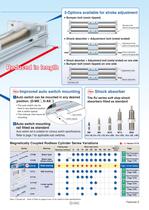
3-Options available for stroke adjustment Bumper bolt (resin tipped) Bumper bolt (Same on the opposite side) Shock absorber + Adjustment bolt (metal ended) Adjustment bolt (Same on the opposite side) Shock absorber (Same on the opposite side) Reduced in length Shock absorber + Adjustment bolt (metal ended) on one side Bumper bolt (resin tipped) on one side Adjustment bolt Shock absorber Bumper bolt New Improved auto switch mounting zAuto switch can be mounted in any desired position. (D-M9 , D-A9 ) • The auto switch can be fixed in any desired position with a switch spacer. • This reduces man-hours...
Open the catalog to page 3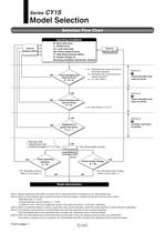
Series CY1S Model Selection Selection Flow Chart Operating Conditions D: Bore size (mm) L: Stroke (mm) m: Load mass (kg) Va: Piston speed (mm/s) P: Operating pressure (MPa) E: Kinetic energy (J) Review the operating conditions. Review the operating conditions. Mounting orientation (Horizontal, Vertical) NG ) mh: Allowable load mass by thrust in horizontal operation mv: Allowable load mass by thrust in vertical operation mh, mv: See Table 1. Check allowable load mass by thrust. m mh, mv OK Reference 1 Check allowable load mass by thrust. Reference 2 NG Check allowable load mass by stroke. Check...
Open the catalog to page 4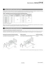
Model Selection Series CY1S 1 Check allowable load mass by thrust. In this series, the work load and the maximum operating pressure are restricted to prevent the magnetic coupling from being separated. Ensure that the work load mass and operating pressure are within the values in Table 1. Table 1. Allowable load mass by thrust and maximum operating pressure Bore size (mm) Horizontal operation Horizontal operation Max. operating pressure mh [kg] Ph [MPa] Note) Vertical operation Max. operating pressure Pv [MPa] Vertical operation mv [kg] 6 1.8 1.0 10 3.0 2.7 15 7.0 20 12 25 20 18.5 32 30 30 40...
Open the catalog to page 5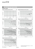
2 Check allowable load mass by stroke. Selection Graph Graph 1] Allowable load mass by stroke Graph 3] Allowable load mass by stroke Graph 5] Allowable load mass by stroke Graph 7] Allowable load mass by stroke Graph 2] Allowable load mass by stroke Graph 4] Allowable load mass by stroke Graph 6] Allowable load mass by stroke : If load center of gravity exceeds the value of y, z + A on the graph, please consult SMC.
Open the catalog to page 6
Model Selection Series CY1S 3 Consider load factor on guides. 3 — q Types of moment applied to rodless cylinders Multiple moments may be generated depending on the mounting orientation, load, and position of the center of gravity. Coordinates and Moments M3: Yaw moment The direction of the axis, X, Y and Z are based on the cylinder mounting orientation shown on the right. Consider the direction of the axis for each mounting direction. Z M1: Pitch moment Y X M2: Roll moment Static moment calculation by mounting style [Horizontal mounting] [Ceiling mounting] M1 M2 y X Y x mxg M1 M2 X [Wall mounting]...
Open the catalog to page 7
3 Consider load factor on guides. Q—(2) Allowable load mass on guides/Allowable moment Table 4. Allowable load mass on guides and moment The table above indicates the maximum performance of the guide, but does not show the actual allowable work load mass. Refer to Graphs (8) to (13) for correct allowable mass by piston speed. Graph 8] Allowable load mass on guides (06 to o15) m Graph 10] Allowable moment (06 to o15) Graph 12] Allowable moment (06 to 015) Graph 9] Allowable load mass on guides (020 to 040) m Graph 11] Allowable moment (020 to 040) Graph 13] Allowable moment (020 to 040)
Open the catalog to page 8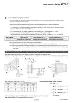
Model Selection Series CY1S 3 — e Consideration of guide load factor Work load mass and allowable moment varies depending on the load mounting method, stroke, cylinder mounting orientation and piston speed. Whether the cylinder is suitable or not is decided by the allowable load mass on guides in the graphs. The selection calculation is shown below. It is necessary to consider i) allowable load mass on guides, ii) static moment and iii) dynamic moment (when the slide block collides with the stopper). i) · ii) is calculated with Va (average speed) and iii) is calculated with V (collision speed...
Open the catalog to page 9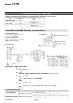
Series CY1S Calculation of Guide Load Factor The selection calculation finds the load factors ( n) of the items below, where the total does not exceed 1. Load factor n Item Note 1: Maximum load mass 1 = m/mmax Examine m. mmax is the max. load mass for Va. 2: Static moment 2 = M/Mmax Examine M1, M2, M3. Mmax is the allowable moment for Va. 3: Dynamic moment 3 = ME/MEmax Examine M1E, M3E. MEmax is the allowable moment for V. Calculation example z Mounting on horizontal wall [1] Operating Conditions CY1SG25-600 Wa: Connection plate t = 10 (1.5 kg) Cylinder: CY1SG25-600 Cushion: Shock absorber Mounting:...
Open the catalog to page 10All SMC PNEUMATIC catalogs and technical brochures
 Vacuum Unit 2024
99 Pages
 Air Cylinder CJ2 Series
117 Pages
 AS-FS Series
36 Pages
 IDF series
12 Pages
 MHL2 Series
24 Pages
 JCM Serie
18 Pages
 EX245 Series
12 Pages
 Pin Cylinder CJP2/CDJP2/CJP
19 Pages
 5 Port Solenoid Valve VQC
63 Pages
 5 Port Solenoid Valve VQ
79 Pages
 SY
SY268 Pages
 5-p0979-0980-hep500
2 Pages
 5-p0977-0978-aep100
2 Pages
 5-p0966-0971-lmu
5 Pages
 5-p0960-0966-alb900
6 Pages
 5-p0956-0960-ald600
5 Pages
 5-p0948-0950-al800
3 Pages
 es70-44c-vx2
52 Pages
 es50-37-kq2
124 Pages
 ex-pcw
23 Pages
 1-p2124-2152-ex510
29 Pages
 1-p2111-2122-ex500
12 Pages
 1-p2063-2073-ex260
11 Pages
 4-p0147-0178-msu-mds
32 Pages
 es20-230b-crb2
59 Pages
 1-p1869-1878-vp3145
10 Pages
 VP300/500/700 series
42 Pages
 1-p1789-1829-vqz100
41 Pages
 1-p1727-1788-syj300
62 Pages
 5 Port Solenoid Valve S0700
111 Pages
 5 Port Solenoid Valve VF
59 Pages
 5 Port Solenoid Valve SV
127 Pages
 VH
VH9 Pages
 CUJ
CUJ41 Pages
 AL
AL3 Pages
 kj mm
kj mm9 Pages
 AQ
AQ4 Pages
 SY3000/5000-X13
2 Pages
 Series MB
24 Pages
 Series LES
23 Pages
 Series LEFB
16 Pages
 Series PF3W
28 Pages
 Series IDG?A/IDG
56 Pages
 Floating Joint
7 Pages
 Series IZS40/41/42
32 Pages
 Series LEY
7 Pages
 Series VHS
12 Pages
 SeriesCQ2/CQS/CQ
4 Pages
 In-line Air Filter
12 Pages
 5 Port Solenoid Valve
60 Pages
 Series CQ2/CQS
2 Pages
 AS series
2 Pages
 corporate guide
13 Pages
 ZP
ZP69 Pages
 ZFA
ZFA14 Pages
 ZA
ZA13 Pages
 MHF
MHF32 Pages
 MHZ
MHZ68 Pages
 CRB
CRB44 Pages
 D
D117 Pages
 RB
RB23 Pages
 CEP
CEP44 Pages
 RSK
RSK30 Pages
 CLK
CLK51 Pages
 MK
MK20 Pages
 GLJ
GLJ65 Pages
 MGJ
MGJ7 Pages
 Mx
Mx36 Pages
 MXH
MXH18 Pages
 My3
My356 Pages
 my1b
my1b20 Pages
 CC
CC15 Pages
 J
J14 Pages
 CQ2
CQ251 Pages
 standard cylinder
84 Pages
 VFN
VFN6 Pages
 SY3000
246 Pages
 SJ3A6
SJ3A618 Pages
 1301/IW
14 Pages
 CHQ/CHDQ
19 Pages
 AC
AC95 Pages
 HAW
HAW4 Pages
 HAA
HAA3 Pages
 ZB
ZB24 Pages
 CRB2
CRB235 Pages


Archived catalogs
 CJ1
CJ15 Pages
 SYJ
SYJ62 Pages
 SJ
SJ78 Pages
 Vacuum Unit ZK2 Series
60 Pages
 SYJ300/500/700 Series
62 Pages
