- Catalogs
- SMC PNEUMATIC
- Pin Cylinder CJP2/CDJP2/CJP
Pin Cylinder CJP2/CDJP2/CJP
1 /19Pages

Pin Cylinder CJP2/CDJP2/CJP
1 /19Pages
Catalog excerpts

2 auto switches can even be mounted on a cylinder with ø4 bore size (5 mm stroke). One-touch fitting can be connected. (Panel mount type) Auto switch ø2 One-touch fitting, miniature fitting, and speed controller can be connected. Double acting / Single acting /
Open the catalog to page 1
Double acting / 6 to 9.5 mm to mm Weight: Reduced by 55 to 65% Weight: Reduced by to % Full length: Shortened by Full length: Shortened by New aluminum body is light weight compared with the conventional CJP series. (Compared with the basic model CJP cylinder without auto switch) Bore size Unit: g Bore size (mm) ): Dimension for built-in magnet type Single acting / Panel mount type (CJPB4-5) Dimensions Bore size Unit: g Bore size (mm) Variation Series Double acting, Single rod Mounting Note 2) Basic Flange Foot Clevis Trunnion Single acting, Spring return Bore size (mm) Standard stroke (mm) Mounting...
Open the catalog to page 2
Pin Cylinder: Double Acting, Single Rod Standard Built-in magnet With auto switch (Built-in magnet) Mounting Mounting Number of auto switches Built-in magnet Basic Flange Foot Clevis Trunnion Auto switch ∗ Bore size of 4 mm is available with basic mounting only. ∗ Mounting bracket is shipped together (but not assembled). ∗ Trunnion mounting type is shipped after Bore assembled. Without auto switch ∗ For the applicable auto switch model, refer to the below table. Cylinder standard stroke (mm) With thread Without thread Double acting Built-in Magnet Cylinder Model CA2 If a built-in magnet cylinder...
Open the catalog to page 3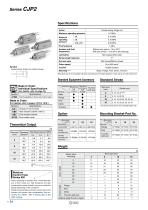
Series CJP2 Specifications Action Double acting, Single rod Maximum operating pressure Minimum operating pressure Proof pressure Ambient and fluid temperature Without auto switch: –10 to 70°C With auto switch: –10 to 60°C (No freezing) Stroke length tolerance Rod end style With thread/Without thread 10 to 500 mm/s∗ Piston speed Double acting, Single rod, Rubber bumper Rubber bumper Mounting Note) Basic, Flange, Foot, Clevis, Trunnion Note) Bore size of ø4 is available with basic mounting only. The piston speed for a bore size of ø4 is 50 to 500 mm/s. Standard Equipment Accessory Made to Order:...
Open the catalog to page 4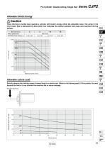
Pin Cylinder: Double Acting, Single Rod Allowable Kinetic Energy Caution When driving an inertial load, operate a cylinder with kinetic energy within the allowable value. The range in the chart below that is delineated by bold solid lines indicates the relation between load mass and maximum driving speeds. 4 Bore size (mm) Piston speed (m/s) Allowable kinetic energy (J) MB1 Allowable Lateral Load Strictly observe the limiting range of lateral load on a piston rod. (Refer to the below graph.) If this product is used beyond the limits, it may shorten the machine life or cause damage. Allowable...
Open the catalog to page 5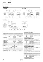
Built-in magnet Built-in magnet Built-in magnet Replacement Parts: Seal Kit Standard Head cover Hard anodized Electroless nickel plated Aluminum alloy Material Aluminum alloy Brass Chromated Tool steel Phosphate coating Seal retainer Special steel Nickel plated Electroless nickel plated Zinc chromated Piston seal Rod seal Piston gasket Magnet retainer Urethane rubber Aluminum alloy Retaining ring ∗ Seal kit includes a grease pack (5 g). Order with the following part number when only the grease pack is needed. Grease pack part number: GR-F-005 (5 g) ∗ Seal kit includes a grease pack (5 g). Order...
Open the catalog to page 6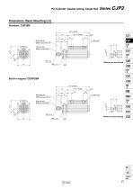
Pin Cylinder: Double Acting, Single Rod Dimensions: Basic Mounting (ø4) Standard: CJP2B4 29 + Stroke 14 7 Mounting nut Width across flats 10 Rod end nut Width across flats 4 Width across flats 10 Rod end nut Width across flats 4
Open the catalog to page 7
Series CJP2 Dimensions: Basic Mounting (ø6 to ø16) Standard: CJP2B6 to 16 Z + Stroke S + Stroke H A' Mounting nut Width across flats B1 Width across flats B2 (mm) Symbol Bore size Built-in magnet: CDJP2B6 to 16 Z + Stroke H Width across flats B1 Width across flats B2 (mm) Symbol Bore size
Open the catalog to page 8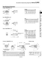
Pin Cylinder: Double Acting, Single Rod Mounting Bracket Dimensions Flange: C(D)JP2F6 to 16 Flange ∗ Other dimensions are the same as basic mounting. ∗ Other dimensions are the same as basic mounting. Symbol Bore size Q øCD with flange bushing (None for ø6) Symbol Bore size Pin hole dia. øCD C-type retaining ring ≈A Mounting dimensions of trunnion bracket Without Built-in Without Built-in Without Built-in magnet magnet magnet magnet magnet magnet Rotation angle ZZ + Stroke Symbol Bore size Without Built-in Without Built-in magnet magnet magnet magnet ∗ Provided as guidelines. The values are varied...
Open the catalog to page 9
Accessory Bracket Dimensions Single knuckle joint Double knuckle joint øND hole H10 Axis d9 Material: Rolled steel Applicable bore size (mm) Applicable bore size A B (mm) ∗ Knuckle pin and retaining ring are included. Material: Rolled steel Material: Stainless steel Applicable bore size (mm) Retaining∗ ring Material: Stainless steel Applicable bore size (mm) Retaining∗ ring Rod end cap Flat type: CJ-CF A Applicable bore size (mm) Material: Brass Round type: CJ-CR A Material: Polyacetal Material: Iron Flat type Applicable bore size (mm) Applicable bore size Round type (mm)
Open the catalog to page 10
Auto Switch Mounting 1 Auto Switch Proper Mounting Position (Detection at Stroke End) and Its Mounting Height D-A9(V), D-M9(V), D-M9W(V), D-M9A(V) Applicable Auto Switches: D-A9, D-A9V A B (When detecting at retracted stroke end position) Bore size (When detecting at extended stroke end position) B (When detecting at retracted stroke end position) Bore size (When detecting at extended Note) Only adjust the setting position after confirming the auto switch is properly activated. Mounting: Basic, Flange, Foot Auto switch model Bore size Mounting: Clevis, Trunnion Auto switch model Bore size ∗ 0...
Open the catalog to page 11
Auto Switch Mounting 2 Operating Range Minimum Stroke for Auto Switch Mounting (mm) (mm) Auto switch model Applicable auto switch model Bore size No. of auto switches mounted ∗ Since the operating range is provided as a guideline including hysteresis, it cannot be guaranteed (assuming approximately ±30% dispersion). It may vary substantially depending on an ambient environment. Mounting and Moving Auto Switches Watchmaker’s screwdriver Auto switch mounting screw q Fit an auto switch into the auto switch mounting groove to set it roughly to the mounting position for an auto switch. w After reconfirming...
Open the catalog to page 12All SMC PNEUMATIC catalogs and technical brochures
 Vacuum Unit 2024
99 Pages
 Air Cylinder CJ2 Series
117 Pages
 AS-FS Series
36 Pages
 IDF series
12 Pages
 MHL2 Series
24 Pages
 JCM Serie
18 Pages
 EX245 Series
12 Pages
 5 Port Solenoid Valve VQC
63 Pages
 5 Port Solenoid Valve VQ
79 Pages
 SY
SY268 Pages
 5-p0979-0980-hep500
2 Pages
 5-p0977-0978-aep100
2 Pages
 5-p0966-0971-lmu
5 Pages
 5-p0960-0966-alb900
6 Pages
 5-p0956-0960-ald600
5 Pages
 5-p0948-0950-al800
3 Pages
 es70-44c-vx2
52 Pages
 es50-37-kq2
124 Pages
 ex-pcw
23 Pages
 1-p2124-2152-ex510
29 Pages
 1-p2111-2122-ex500
12 Pages
 1-p2063-2073-ex260
11 Pages
 4-p0147-0178-msu-mds
32 Pages
 es20-230b-crb2
59 Pages
 1-p1869-1878-vp3145
10 Pages
 VP300/500/700 series
42 Pages
 1-p1789-1829-vqz100
41 Pages
 1-p1727-1788-syj300
62 Pages
 5 Port Solenoid Valve S0700
111 Pages
 5 Port Solenoid Valve VF
59 Pages
 5 Port Solenoid Valve SV
127 Pages
 VH
VH9 Pages
 CUJ
CUJ41 Pages
 AL
AL3 Pages
 kj mm
kj mm9 Pages
 AQ
AQ4 Pages
 SY3000/5000-X13
2 Pages
 Series MB
24 Pages
 Series LES
23 Pages
 Series LEFB
16 Pages
 Series PF3W
28 Pages
 Series IDG?A/IDG
56 Pages
 Floating Joint
7 Pages
 Series IZS40/41/42
32 Pages
 Series LEY
7 Pages
 Series VHS
12 Pages
 Series CY1S
28 Pages
 SeriesCQ2/CQS/CQ
4 Pages
 In-line Air Filter
12 Pages
 5 Port Solenoid Valve
60 Pages
 Series CQ2/CQS
2 Pages
 AS series
2 Pages
 corporate guide
13 Pages
 ZP
ZP69 Pages
 ZFA
ZFA14 Pages
 ZA
ZA13 Pages
 MHF
MHF32 Pages
 MHZ
MHZ68 Pages
 CRB
CRB44 Pages
 D
D117 Pages
 RB
RB23 Pages
 CEP
CEP44 Pages
 RSK
RSK30 Pages
 CLK
CLK51 Pages
 MK
MK20 Pages
 GLJ
GLJ65 Pages
 MGJ
MGJ7 Pages
 Mx
Mx36 Pages
 MXH
MXH18 Pages
 My3
My356 Pages
 my1b
my1b20 Pages
 CC
CC15 Pages
 J
J14 Pages
 CQ2
CQ251 Pages
 standard cylinder
84 Pages
 VFN
VFN6 Pages
 SY3000
246 Pages
 SJ3A6
SJ3A618 Pages
 1301/IW
14 Pages
 CHQ/CHDQ
19 Pages
 AC
AC95 Pages
 HAW
HAW4 Pages
 HAA
HAA3 Pages
 ZB
ZB24 Pages
 CRB2
CRB235 Pages


Archived catalogs
 CJ1
CJ15 Pages
 SYJ
SYJ62 Pages
 SJ
SJ78 Pages
 Vacuum Unit ZK2 Series
60 Pages
 SYJ300/500/700 Series
62 Pages
