- Catalogs
- SMC PNEUMATIC
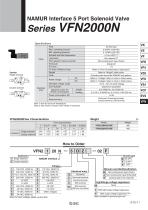
- NAMUR Interface 5 Port Solenoid Valve VFN2000N
NAMUR Interface 5 Port Solenoid Valve VFN2000N
1 /4Pages

NAMUR Interface 5 Port Solenoid Valve VFN2000N
1 /4Pages
Catalog excerpts
NAMUR Interface 5 Port Solenoid Valve Symbol Single solenoid 42 Double solenoid Electrical entry Fluid Max. operating pressure Min. operating pressure Ambient and fluid temperature Lubrication Pilot operator manual override Enclosure Port size Cv factor (Effective area) Weight Other AC Rated voltage DC Allowable voltage range Coil insulation Inrush Apparent power AC (Power consumption) Holding Power consumption DC Electrical entry Air/Inert gas 0.9 MPa {130 PSI} 0.15 MPa {22 PSI} –10 to +60°C (1) Not required (2) Non-locking push type (Flush) Dustproof 1/4 Refer to “Flow Characteristics” table below. Refer to “Weight” table below. Cylinder ports should be NAMUR hole pattern. Refer to “Voltage” table on How to Order below. Refer to “Voltage” table on How to Order below. –15 to +10% of rated voltage Class B or equivalent 5.0 VA/60 Hz, 5.6 VA/50 Hz 2.3 VA (1.5 W)/60 Hz, 3.4 VA (2.1 W) 9/50 Hz 1.8 W Grommet, Grommet terminal, Conduit terminal, DIN terminal Note 1) Use dry-air at low temperature. Note 2) Use turbine oil Class1 (ISO VG32), if lubricated. Flow characteristics 1 Ǟ 4/2 (P Ǟ A/B) 4/2 Ǟ 5/3 (A/B Ǟ EA/EB) C b Cv C b Cv 3.48 0.25 0.85 4.57 0.17 1.06 3.48 0.25 0.85 4.57 0.17 1.06 Single solenoid Double solenoid Solenoid NAMUR Interface 1 Single solenoid 2 Double solenoid Note) For other voltages, please contact SMC. Manual override/Classification Electrical entry G E T D DO Grommet Grommet terminal Conduit terminal DIN terminal DIN terminal (Without connector) Nil Non-locking push type (Flush) A Non-locking push type (Extended) Locking type (Tool required) B Light/Surge voltage suppressor Nil Z With light/surge voltage suppressor S With surge voltage suppressor Note) Note) Available for grommet type only.
Open the catalog to page 1
Applicable heavy-duty cord O.D.ø6 to ø8 Manual override (Non-locking) Applicable heavy-duty cord O.D.ø6 to ø8 Pg9 Manual override (Non-locking) ∗ Cylinder ports are NAMUR hole pattern.
Open the catalog to page 2
NAMUR Interface 5 Port Solenoid Valve NAMUR Mounting Pattern Axis A-A' can be aligned to suit. VK M5 thread 8 deep, with or without insert depending on base material. Drive flange face Solenoid valve flange face The solenoid valve can be attached with 2 mounting bolts. The positioning of the coding stud hole is left up to the manufacture and thus also determines the location of the coding stud.
Open the catalog to page 3
Specific Product Precautions Be sure to read before handling. Environmental Conditions 1. When piping, please use I.D. equivalent to or larger than N.B. 2. Before piping, flush the system to remove dust, scale, chips, seal tape etc. in the pipe line both on the supply side (supply pressure port side) and secondary side (operation equipment port side). 3. For 3 position closed center, perfect check valve, check for leakage from piping and fittings in-between valve and cylinder by means of soapy water to ensure that there is no leakage. Also check the leakage from cylinder rod seal and piston seal....
Open the catalog to page 4All SMC PNEUMATIC catalogs and technical brochures
 Vacuum Unit 2024
99 Pages
 Air Cylinder CJ2 Series
117 Pages
 AS-FS Series
36 Pages
 IDF series
12 Pages
 MHL2 Series
24 Pages
 JCM Serie
18 Pages
 EX245 Series
12 Pages
 Pin Cylinder CJP2/CDJP2/CJP
19 Pages
 5 Port Solenoid Valve VQC
63 Pages
 5 Port Solenoid Valve VQ
79 Pages
 SY
SY268 Pages
 5-p0979-0980-hep500
2 Pages
 5-p0977-0978-aep100
2 Pages
 5-p0966-0971-lmu
5 Pages
 5-p0960-0966-alb900
6 Pages
 5-p0956-0960-ald600
5 Pages
 5-p0948-0950-al800
3 Pages
 es70-44c-vx2
52 Pages
 es50-37-kq2
124 Pages
 ex-pcw
23 Pages
 1-p2124-2152-ex510
29 Pages
 1-p2111-2122-ex500
12 Pages
 1-p2063-2073-ex260
11 Pages
 4-p0147-0178-msu-mds
32 Pages
 es20-230b-crb2
59 Pages
 1-p1869-1878-vp3145
10 Pages
 VP300/500/700 series
42 Pages
 1-p1789-1829-vqz100
41 Pages
 1-p1727-1788-syj300
62 Pages
 5 Port Solenoid Valve S0700
111 Pages
 5 Port Solenoid Valve VF
59 Pages
 5 Port Solenoid Valve SV
127 Pages
 VH
VH9 Pages
 CUJ
CUJ41 Pages
 AL
AL3 Pages
 kj mm
kj mm9 Pages
 AQ
AQ4 Pages
 SY3000/5000-X13
2 Pages
 Series MB
24 Pages
 Series LES
23 Pages
 Series LEFB
16 Pages
 Series PF3W
28 Pages
 Series IDG?A/IDG
56 Pages
 Floating Joint
7 Pages
 Series IZS40/41/42
32 Pages
 Series LEY
7 Pages
 Series VHS
12 Pages
 Series CY1S
28 Pages
 SeriesCQ2/CQS/CQ
4 Pages
 In-line Air Filter
12 Pages
 5 Port Solenoid Valve
60 Pages
 Series CQ2/CQS
2 Pages
 AS series
2 Pages
 corporate guide
13 Pages
 ZP
ZP69 Pages
 ZFA
ZFA14 Pages
 ZA
ZA13 Pages
 MHF
MHF32 Pages
 MHZ
MHZ68 Pages
 CRB
CRB44 Pages
 D
D117 Pages
 RB
RB23 Pages
 CEP
CEP44 Pages
 RSK
RSK30 Pages
 CLK
CLK51 Pages
 MK
MK20 Pages
 GLJ
GLJ65 Pages
 MGJ
MGJ7 Pages
 Mx
Mx36 Pages
 MXH
MXH18 Pages
 My3
My356 Pages
 my1b
my1b20 Pages
 CC
CC15 Pages
 J
J14 Pages
 CQ2
CQ251 Pages
 standard cylinder
84 Pages
 VFN
VFN6 Pages
 SY3000
246 Pages
 SJ3A6
SJ3A618 Pages
 1301/IW
14 Pages
 CHQ/CHDQ
19 Pages
 AC
AC95 Pages
 HAW
HAW4 Pages
 HAA
HAA3 Pages
 ZB
ZB24 Pages
 CRB2
CRB235 Pages


Archived catalogs
 CJ1
CJ15 Pages
 SYJ
SYJ62 Pages
 SJ
SJ78 Pages
 Vacuum Unit ZK2 Series
60 Pages
 SYJ300/500/700 Series
62 Pages
