My3
1 /56Pages

My3
1 /56Pages
Catalog excerpts
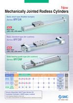
Mechanically Jointed Rodless Cylinders Basic short type (Rubber bumper) Bore sizes Basic standard type (Air cushion) Bore sizes Slide bearing guide type (Air cushion) Series Variations Long stroke Shock Absorber "Helical Insert threads" Holder mounting bracketNo,e) Copper Free Shock Absorber Soft Type Series RJ Installed Cylinder (-XB22 spec.) added • Soft stopping enabled at stroke end. • Two types of shock absorbers are selectable according to operating environment.
Open the catalog to page 1
High functionality with reduced height and length Mechanically Jointed Rodless Cylinders Basic short type (Rubber bumper) Basic standard type Loading Capacity Work pieces can be loaded directly on the work table Overall length (Z) reduced by mm at the maximum MY3A (with rubber bumper) _ Overall length (Z + Stroke) Height (H) reduced by 36% at the maximum Weight reduced by 55% at the maximum
Open the catalog to page 2
Floating Bracket Easy connection with external guide. Vertical and lateral mounting is possible. (Page 24) Stroke Adjustment Unit (MY3A/3B) (MY3B/3M) Side Support The cylinder tube can be fixed from the upper or lower side. (Page 23, 37) Auto Switch Centralized Piping Integrated piping in the head cover is possible. (Page 20, 21, 35) Can be mounted on both sides from the front direction. The uniquely designed piston shape enables reduction of the height and length as well as practical arrangement of the common piping passages, cushion mechanism and positioning mechanism. This has achieved drastic...
Open the catalog to page 3
Model Selection The following are steps for selecting the MY3 series which is best suited to your application. Guideline for Tentative Model Selection O Most suitable O Suitable A Usable X Not recommended Note 1 ) The table accuracy means the amount of table deflection when a moment Is applied. Note 2) Travelling parallelism Is not guaranteed for this cylinder. Please consult with SMC If the travelling parallelism or stroke Intermediate position needs to be precise. Selection Flow Chart When an external guide is used, the selection confirmation of the guide capacity should follow the selection...
Open the catalog to page 4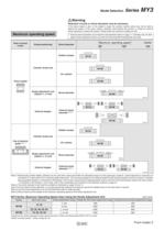
Model Selection Seríes MY3 Maximum operating speed Reduction circuits or shock absorbers may be necessary. If the driven object is fast, or the weight is large, the cylinder cushion alone may not be able to absorb the Impact. In this case, install a reduction circuit before the cushion, or Install an external shock absorber to reduce the Impact. Please check the machine's rigidity as well. * External shock absorbers must meet the characteristics listed on page 11. Cylinders may be dam- aged If shock absorbers that do not have the recommended characteristics are used. Stroke positioning Shock...
Open the catalog to page 5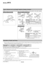
Types of Moment and Load Weight Applied to Rodless Cylinders Multiple moments may be generated depending on the mounting orientation, load and position of the center of gravity. Load Weight and Static Moment Note) nu is a weight movable by thrust. Use 0.3 to 0.7 times the thrust (differs depending on the operating speed) as a guide for actual Dynamic Moment Note) Regardless of the mounting orientation, dynamic moment is calculated with the formulae above. Calculation of Guide Load Factor 1. Maximum load weight (1 ), static moment (2), and dynamic moment (3) (at the time of impact with stopper)...
Open the catalog to page 6
Model Selection Series MY3 Calculation of Guide Load Factor 1 Operating Conditions Cylinder • • • • • • • • • • • • • • • • • • • • • • • • • • • • • • • • • • • • • • Average operating speed υa • • • • • • • • • • Mounting direction • • • • • • • • • • • • • • • • • • • • • • • Cushion • • • • • • • • • • • • • • • • • • • • • • • • • • • • • • • • • • • • • • Mounting Direction MY3A25-500 300 mm/s Horizontal mounting Rubber bumper (δ = 4/100) 1. Horizontal z mounting 2. Wall mounting y Page 26 x y 3. Ceiling mounting z x W: Work piece (0.8 kg) 4. Vertical mounting x Page 2 z y x y z MY3A25-500...
Open the catalog to page 7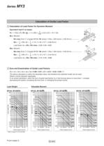
Series MY3 Calculation of Guide Load Factor 4 Calculation of Load Factor for Dynamic Moment Equivalent load FE at impact 4 FE = 1.4υa x δ x m x g = 1.4 x 300 x —— x 0.8 x 9.8 = 131.7 (N) 100 M1E: Moment FE M1E Z M1E max (from r of graph MY3A ⁄ M1 where 1.4υa = 420 mm/s) = 2.85 (NႧm) • • • • • • • • • • • • • • 1 1 M1E = —— x FE x Z = —— x 131.7 x 20 x 10-3 = 0.88 (NႧm) 3 3 Load factor 4 = M1E ⁄ M1E max = 0.88 ⁄ 2.85 = 0.31 M1 M3 M3E: Moment Y M3E max (from t of graph MY3A ⁄ M3 where 1.4υa = 420 mm/s) = 0.95 (NႧm) • • • • • • • • • • • • • • • • • • • • 1 1 M3E = —— x FE x Y = —— x 131.7 x 10...
Open the catalog to page 8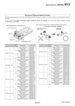
Model Selection Seríes MY3 Mounting of Fitting and Speed Controller When the stroke adjustment unit is used with MY3B and MY3M, the fittings mountable on the front or back port will be limited to those lis- In such cases, since direct mount type speed controllers cannot be mounted, use in-line type speed controllers. (Except Mounting (Mounting a male connector) Stroke adjustment unit Refer to Best Pneumatics No. 6 for the details of fittings and speed controllers. Direct Mount Type Speed Controller Elbow/Universal type In-line type
Open the catalog to page 9
Specific Product Precautions Be sure to read before handling. Refer to back cover for the Safety Instructions, "Handling Precautions for SMC Products" (M-E03-3) and the Operation Manual for Actuators and Auto Switches Precautions. 1. When applying a load directly, set the design so that all the mounting threads on the slide table's upper surface are used. Parts have been made smaller to achieve a compact size. If only some of the threads are used when mounting the load, the impact that results from the operation may cause extreme- ly concentrated stress or disfiguration and may negatively af-...
Open the catalog to page 10All SMC PNEUMATIC catalogs and technical brochures
 Vacuum Unit 2024
99 Pages
 Air Cylinder CJ2 Series
117 Pages
 AS-FS Series
36 Pages
 IDF series
12 Pages
 MHL2 Series
24 Pages
 JCM Serie
18 Pages
 EX245 Series
12 Pages
 Pin Cylinder CJP2/CDJP2/CJP
19 Pages
 5 Port Solenoid Valve VQC
63 Pages
 5 Port Solenoid Valve VQ
79 Pages
 SY
SY268 Pages
 5-p0979-0980-hep500
2 Pages
 5-p0977-0978-aep100
2 Pages
 5-p0966-0971-lmu
5 Pages
 5-p0960-0966-alb900
6 Pages
 5-p0956-0960-ald600
5 Pages
 5-p0948-0950-al800
3 Pages
 es70-44c-vx2
52 Pages
 es50-37-kq2
124 Pages
 ex-pcw
23 Pages
 1-p2124-2152-ex510
29 Pages
 1-p2111-2122-ex500
12 Pages
 1-p2063-2073-ex260
11 Pages
 4-p0147-0178-msu-mds
32 Pages
 es20-230b-crb2
59 Pages
 1-p1869-1878-vp3145
10 Pages
 VP300/500/700 series
42 Pages
 1-p1789-1829-vqz100
41 Pages
 1-p1727-1788-syj300
62 Pages
 5 Port Solenoid Valve S0700
111 Pages
 5 Port Solenoid Valve VF
59 Pages
 5 Port Solenoid Valve SV
127 Pages
 VH
VH9 Pages
 CUJ
CUJ41 Pages
 AL
AL3 Pages
 kj mm
kj mm9 Pages
 AQ
AQ4 Pages
 SY3000/5000-X13
2 Pages
 Series MB
24 Pages
 Series LES
23 Pages
 Series LEFB
16 Pages
 Series PF3W
28 Pages
 Series IDG?A/IDG
56 Pages
 Floating Joint
7 Pages
 Series IZS40/41/42
32 Pages
 Series LEY
7 Pages
 Series VHS
12 Pages
 Series CY1S
28 Pages
 SeriesCQ2/CQS/CQ
4 Pages
 In-line Air Filter
12 Pages
 5 Port Solenoid Valve
60 Pages
 Series CQ2/CQS
2 Pages
 AS series
2 Pages
 corporate guide
13 Pages
 ZP
ZP69 Pages
 ZFA
ZFA14 Pages
 ZA
ZA13 Pages
 MHF
MHF32 Pages
 MHZ
MHZ68 Pages
 CRB
CRB44 Pages
 D
D117 Pages
 RB
RB23 Pages
 CEP
CEP44 Pages
 RSK
RSK30 Pages
 CLK
CLK51 Pages
 MK
MK20 Pages
 GLJ
GLJ65 Pages
 MGJ
MGJ7 Pages
 Mx
Mx36 Pages
 MXH
MXH18 Pages
 my1b
my1b20 Pages
 CC
CC15 Pages
 J
J14 Pages
 CQ2
CQ251 Pages
 standard cylinder
84 Pages
 VFN
VFN6 Pages
 SY3000
246 Pages
 SJ3A6
SJ3A618 Pages
 1301/IW
14 Pages
 CHQ/CHDQ
19 Pages
 AC
AC95 Pages
 HAW
HAW4 Pages
 HAA
HAA3 Pages
 ZB
ZB24 Pages
 CRB2
CRB235 Pages


Archived catalogs
 CJ1
CJ15 Pages
 SYJ
SYJ62 Pages
 SJ
SJ78 Pages
 Vacuum Unit ZK2 Series
60 Pages
 SYJ300/500/700 Series
62 Pages
