my1b
1 /20Pages

my1b
1 /20Pages
Catalog excerpts
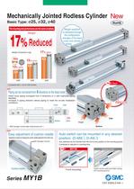
Mechanically Jointed Rodless Cylinder New Basic Type: ø25, ø32, ø40 RoHS The mounting and performance are the same as before. Weight reduction is achieved through the configuration changes of the head cover and cylinder tubing. 17% Reduced Weight 17% lighter Weight comparison (kg) 9.9 New MY1B Conventional model 13% lighter 3.4 13% lighter 5.8 8.2 6.7 3.9 ø25 ø32 ø40 New Back Compared with L unit at 1000 strokes. New Piping can be connected from 4 directions on the head cover Head cover piping increased from 3 directions to 4 with improved piping flexibility. Increase in piping direction allows piping to meet the on-site installation conditions. Front Piping ports Side New Bottom Back Side Front Bottom With hexagon socket taper plug except port 1. New Easy adjustment of cushion needle Adjustment is easier by changing the cushion needle adjustment from side to top. Hexagon wrench Auto switch can be mounted in any desired position. (D-M9 , D-A9 ) Auto switches can be mounted from the front at any position on the mounting groove. Contributes to reduction in mounting time. New Cushion needle Series MY1B MY1B Existing model Front mounting Insert it at the notch and slide it along the mounting groove. CAT.ES20-210A
Open the catalog to page 1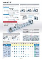
Improvement of port variations With addition of the back port, piping can be connected to suit the installation conditions. Stroke adjustment unit The stroke can be adjusted at one side and both sides. • With adjustment bolt • With low/high load shock absorber + adjustment bolt (L/H unit) Standard piping type Operating direction <^ZT] Front Centralized piping type Operating direction Intermediate fixing spacer as standard Fixture can be selected to hold the stroke adjustment unit at the intermediate stroke position. proved shock-less character when a work piece is stopped. Soft type of shock...
Open the catalog to page 2
Maximum Allowable Moment/Maximum Load Mass The above values are the maximum allowable values for moment and load mass. Refer to each graph regarding the maximum allowable moment and maximum load mass for a particular piston speed. Load mass(kg) 1. We recommend an external shock ab- sorber be installed when the cylinder is combined with another guide (connection with floating bracket, etc.) and the maxi- mum load mass is exceeded. 2. Load factor of 0.5 or less When the load factor is high against the cylinder output, it may adversely affect the cylinder (condensation, etc.) and cause malfunctions....
Open the catalog to page 3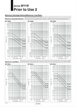
Maximum Allowable Moment/Maximum Load Mass Select the moment from within the range of operating limits shown in the graphs. Note that the maximum load mass value may sometimes Màximum All0Wabl6 Moment be exceeded even within the operating limits shown In the graphs. Therefore, also check the load mass for the selected conditions. Select the load mass from within the range of limits shown in the graphs. Note that the maximum allowable moment value may sometimes Màximum Load MaSS be exceeded even within the operating limits shown In the graphs. Therefore, also check the allowable moment for the...
Open the catalog to page 4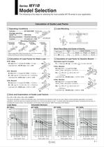
Model Selection The following is the steps for selecting the most suitable MY1B series to your application. Calculation of Guide Load Factor Mounting orientation — Horizontal mounting ---------------Mounting Orientation mounting mounting mounting Refer to page 948 in Best Pneumatics No. 2 for wall mounting, celling mounting and vertical mounting types. Work Piece Mass and Center of Gravity [^Calculation of Load Factor for Static Load Load factor Oli = mi/mi max = 2/27 = 0.07 [~4] Calculation of Load Factor for Dynamic Moment — Equivalent load FE at impact MiEmax (from©of graph MYIB/M1 Load factor...
Open the catalog to page 5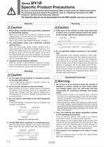
Specific Product Precautions Be sure to read the below before handling. Refer to back cover for Safety Instructions. For Actuator and Auto Switch Precautions, refer to "Handling Precautions for SMC Products" (M-E03-3) and Operation Manual. The Operation Manual can be downloaded from the SMC website, http://www.smcworld.com When using a cylinder with long strokes, implement When using a cylinder with long strokes, implement an inter- mediate support to prevent the tube from sagging and being deflected by vibration or an external load. Refer to the "Guide to Side Support Application" on page 12....
Open the catalog to page 6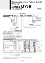
Mechanically Jointed Rodless Cylinder Basic Type Basic type Basic typel" Bore size Port thread type Refer to the next page Number of auto switches Auto switch Nil I Without auto switch (Built-in magnet) | Stroke adjustment unit symbol For stroke adjustment unit, refer to page 6. * Strokes are manufacturable in 1 mm increments, up to the maximum stroke. However, please be advised that with stroke 49 or less, there are cases where auto switch mounting is not possible and the performance of the air cushion may decline. Also when exceeding a 2000 mm stroke, specify "-XB11" at the end of the part...
Open the catalog to page 7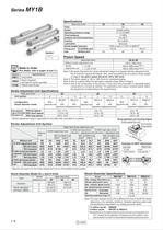
Piston Speed (For details, refer to pages 16 and 17.) Stroke Adjustment Unit Specifications Note 1) Be aware that when the stroke adjustment range is increased with the adjustment bolt, the air cushion capacity decreases. Also, when exceeding the air cushion stroke ranges on page 8, the piston speed should be 100 to 200 mm/s. Note 2) The piston speed is 100 to 1000 mm/s for centralized piping. Note 3) Use at a speed within the absorption capacity range. Refer to page 8. Note 4) Due to the construction of this product, it may have more fluctuation in operating speed compared to a rod type air...
Open the catalog to page 8
Mechanically Jointed Rodless Cylinder Basic Type Theoretical Output Note) Theoretical output (N) = Pressure (MPa) x Piston area (mm2) Stroke Adjustment Unit/Part No. Stroke adjustment Bore size* Note) For details about adjustment range, • Intermediate fixing spacer Spacer delivery style Stroke adjustment unit Intermediate fixing spacer ♦Spacers are used to fix the stroke adjustment unit at an intermediate stroke position. Component Parts Without Spacer With short spacer Short spacer With long spacer Short spacer only Short spacer Long spacer only Long spacer Long spacer For details about the...
Open the catalog to page 9All SMC PNEUMATIC catalogs and technical brochures
 Vacuum Unit 2024
99 Pages
 Air Cylinder CJ2 Series
117 Pages
 AS-FS Series
36 Pages
 IDF series
12 Pages
 MHL2 Series
24 Pages
 JCM Serie
18 Pages
 EX245 Series
12 Pages
 Pin Cylinder CJP2/CDJP2/CJP
19 Pages
 5 Port Solenoid Valve VQC
63 Pages
 5 Port Solenoid Valve VQ
79 Pages
 SY
SY268 Pages
 5-p0979-0980-hep500
2 Pages
 5-p0977-0978-aep100
2 Pages
 5-p0966-0971-lmu
5 Pages
 5-p0960-0966-alb900
6 Pages
 5-p0956-0960-ald600
5 Pages
 5-p0948-0950-al800
3 Pages
 es70-44c-vx2
52 Pages
 es50-37-kq2
124 Pages
 ex-pcw
23 Pages
 1-p2124-2152-ex510
29 Pages
 1-p2111-2122-ex500
12 Pages
 1-p2063-2073-ex260
11 Pages
 4-p0147-0178-msu-mds
32 Pages
 es20-230b-crb2
59 Pages
 1-p1869-1878-vp3145
10 Pages
 VP300/500/700 series
42 Pages
 1-p1789-1829-vqz100
41 Pages
 1-p1727-1788-syj300
62 Pages
 5 Port Solenoid Valve S0700
111 Pages
 5 Port Solenoid Valve VF
59 Pages
 5 Port Solenoid Valve SV
127 Pages
 VH
VH9 Pages
 CUJ
CUJ41 Pages
 AL
AL3 Pages
 kj mm
kj mm9 Pages
 AQ
AQ4 Pages
 SY3000/5000-X13
2 Pages
 Series MB
24 Pages
 Series LES
23 Pages
 Series LEFB
16 Pages
 Series PF3W
28 Pages
 Series IDG?A/IDG
56 Pages
 Floating Joint
7 Pages
 Series IZS40/41/42
32 Pages
 Series LEY
7 Pages
 Series VHS
12 Pages
 Series CY1S
28 Pages
 SeriesCQ2/CQS/CQ
4 Pages
 In-line Air Filter
12 Pages
 5 Port Solenoid Valve
60 Pages
 Series CQ2/CQS
2 Pages
 AS series
2 Pages
 corporate guide
13 Pages
 ZP
ZP69 Pages
 ZFA
ZFA14 Pages
 ZA
ZA13 Pages
 MHF
MHF32 Pages
 MHZ
MHZ68 Pages
 CRB
CRB44 Pages
 D
D117 Pages
 RB
RB23 Pages
 CEP
CEP44 Pages
 RSK
RSK30 Pages
 CLK
CLK51 Pages
 MK
MK20 Pages
 GLJ
GLJ65 Pages
 MGJ
MGJ7 Pages
 Mx
Mx36 Pages
 MXH
MXH18 Pages
 My3
My356 Pages
 CC
CC15 Pages
 J
J14 Pages
 CQ2
CQ251 Pages
 standard cylinder
84 Pages
 VFN
VFN6 Pages
 SY3000
246 Pages
 SJ3A6
SJ3A618 Pages
 1301/IW
14 Pages
 CHQ/CHDQ
19 Pages
 AC
AC95 Pages
 HAW
HAW4 Pages
 HAA
HAA3 Pages
 ZB
ZB24 Pages
 CRB2
CRB235 Pages


Archived catalogs
 CJ1
CJ15 Pages
 SYJ
SYJ62 Pages
 SJ
SJ78 Pages
 Vacuum Unit ZK2 Series
60 Pages
 SYJ300/500/700 Series
62 Pages
