MXH
1 /18Pages

MXH
1 /18Pages
Catalog excerpts
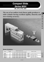
The use of an endless track linear guide produces a table cylinder having excellent rigidity, linearity and non-rotating accuracy. Series Variations
Open the catalog to page 1
The use of an endless track linear guide produces a table cylinder j§ having excellent rigidity, linearity, non-rotating accuracy. Compact Slide Series MX H i Improved moment Allowable moment is approximately 6 times greater than the MXU series. Mounting is possible from Piping is possible from Lateral mounting (through holes) Lateral mounting (tapped holes) Vertical mounting (tapped holes) Axial mounting (tapped holes) If changing the port positions, a made-to-order part number, -XC3D, is available. Applicable example A table cylinder suitable for short pitch mounting Lateral mounting (Body...
Open the catalog to page 2
Model Selection Confirmation of theoretical output is required separately. Refer to "Theoretical Output" on page 21. Selection Conditions: Follow the tables below in order to determine selection conditions and choose one selection graph. Mounting orientation Selection graph • L: Overhang (the distance from the cylinder shaft center to the load center of gravity) The direction of L can also be a diagonal direction. (See the drawing at right.) Selection Graph (1) to (3) (Vertical Mounting) Load center Graph (1) Maximum Speed 100 (mm/s) or Less Graph (3) Maximum Speed 500 (mm/s) or Less Graph (2)...
Open the catalog to page 3
Compact Slide Seríes MXH Selection Graph (4) to (12) (Horizontal Mounting) Maximum Speed 100 mm/s or Less Graph (4) Load Eccentricity 50 mm Maximum Speed 300 mm/s or Less Graph (7) Load Eccentricity 50 mm Maximum Speed 500 mm/s or Less Graph (10) Load Eccentricity 50 mm Graph (5) Load Eccentricity 100 mm Graph (6) Load Eccentricity 200 mm Graph (8) Load Eccentricity 100 mm Graph (9) Load Eccentricity 200 mm Graph (11) Load Eccentricity 100 mm Graph (12) Load Eccentricity 200 mm Selection Example 1. Selection conditions f Mounting: Vertical Refer to Graph (3) based on vertical mounting and a speed...
Open the catalog to page 4
Compact Slide Compact slide Bore size Refer to page 21 for details. Number of auto switches Auto switch Nil I Without auto switch (Built-in magnet) i- For the applicable auto switch model, refer to the table below. Refer to "Standard Stroke" on the next page. Applicable AutO Switch/Refer to pages 1719 to I827 for further information on auto switches. » Water resistant type auto switches can be mounted on the above models, but in such case SMC cannot guarantee water resistance. Consult with SMC regarding water resistant types with the above model numbers. ■ Refer to page 29 for applicable auto...
Open the catalog to page 5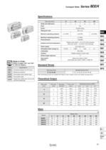
Compact Slide Seríes MXH Ifrfrf I (Refer to pages 1847, and 1851 Standard Stroke Note: Intermediate strokes are available with "Made to Order" models (-XC19). (For details, see page 1916.) Theoretical Output
Open the catalog to page 6
Table Displacement Table Displacement due to Pitch Moment Table Displacement due to Yaw Moment Table displacement (arrow) when a load acts upon the section marked with the arrow at the full stroke of the compact slide Table displacement (arrow) when a load acts upon the section marked with the arrow at the full stroke of the compact slide /KCflUtion I Caution on DesigrT 1. Selection of a bore size cannot be made only with above graphs. Select a bore size in accordance with "Model Selection" on page 18 and 19. 2. Displacement may increase after an impact load has been applied. When the table is...
Open the catalog to page 7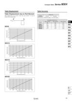
Compact Slide Seríes MXH Table Displacement Table Accuracy Table Displacement due to Roll Moment Table displacement (at A) when a load acts upon section F at the full stroke of the compact slide
Open the catalog to page 8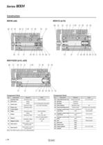
Component Parts Component Parts Note: The MXH series cannot be disassembled.
Open the catalog to page 9
Compact Slide Seríes MXH Plug for port (Hexagon socket head set screw) Guide rail width 5
Open the catalog to page 10
Compact Slide Seríes MXH Plug for port (Hexagon socket head set screw) Guide rail width 9
Open the catalog to page 12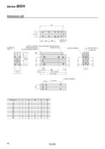
3 X M6 X 1.0 through Plug for port (Hexagon socket head set screw' Guide rail width 12
Open the catalog to page 13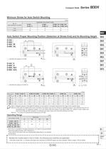
Compact Slide Seríes MXH Minimum Stroke for Auto Switch Mounting Auto Switch Proper Mounting Position (Detection at Stroke End) and Its Mounting Height Note 1) Negative figures in the table W indicate an auto switch is mounted inward from the edge of the cylinder body. Note 2) In the case of models with 5 and 10 strokes, the switch may not turn off due to operating range or two switches may turn on simultaneously. Fix switches outside 1 to 4 mm further than the values in the above table, (if 1 switch is used, make sure that it turns ON and OFF properly; if 2 switches are used, make sure that...
Open the catalog to page 14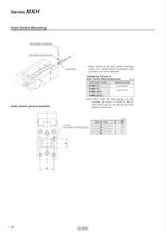
Auto Switch Mounting Watchmaker's screwdriver Auto switch groove position • When tightening the auto switch mounting screw, use a watchmaker's screwdriver with Auto Switch Mounting Screw Note) When used with side piping, it is not auto switch type on the side to which the Auto switch mounting groove
Open the catalog to page 15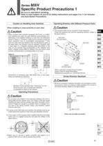
Specific Product Precautions 1 Be sure to read before handling. Refer to front matters 42 and 43 for Safety Instructions and pages 3 to 11 for Actuator and Auto Switch Precautions. Caution on Handling Auto Switches When installing in close proximity to each other 1. When compact slide cylinders equipped with D-A9D or D-M9D auto switches are used, the auto switches could activate unin- tentionally if the installed distance is less than the dimension shown in Table (1). Therefore, make sure to provide at least this much clearance. Due to unavoidable circumstances, if they must be used with less...
Open the catalog to page 16
Specific Product Precautions 2 Be sure to read before handling. Refer to front matters 42 and 43 for Safety Instructions and pages 3 to 11 for Actuator and Auto Switch Precautions. 1. When tightening threads for compact slide, properly tighten within the specified torque. How to Mount a Compact Slide A compact slide can be mounted from 4 directions. Make a selection suitable for the applicable machinery and workpieces, etc. Lateral Mounting (Body through-hole) Lateral Mounting (Body tapped) Vertical Mounting (Body tapped) Axial Mounting (Body tapped)
Open the catalog to page 17All SMC PNEUMATIC catalogs and technical brochures
 Vacuum Unit 2024
99 Pages
 Air Cylinder CJ2 Series
117 Pages
 AS-FS Series
36 Pages
 IDF series
12 Pages
 MHL2 Series
24 Pages
 JCM Serie
18 Pages
 EX245 Series
12 Pages
 Pin Cylinder CJP2/CDJP2/CJP
19 Pages
 5 Port Solenoid Valve VQC
63 Pages
 5 Port Solenoid Valve VQ
79 Pages
 SY
SY268 Pages
 5-p0979-0980-hep500
2 Pages
 5-p0977-0978-aep100
2 Pages
 5-p0966-0971-lmu
5 Pages
 5-p0960-0966-alb900
6 Pages
 5-p0956-0960-ald600
5 Pages
 5-p0948-0950-al800
3 Pages
 es70-44c-vx2
52 Pages
 es50-37-kq2
124 Pages
 ex-pcw
23 Pages
 1-p2124-2152-ex510
29 Pages
 1-p2111-2122-ex500
12 Pages
 1-p2063-2073-ex260
11 Pages
 4-p0147-0178-msu-mds
32 Pages
 es20-230b-crb2
59 Pages
 1-p1869-1878-vp3145
10 Pages
 VP300/500/700 series
42 Pages
 1-p1789-1829-vqz100
41 Pages
 1-p1727-1788-syj300
62 Pages
 5 Port Solenoid Valve S0700
111 Pages
 5 Port Solenoid Valve VF
59 Pages
 5 Port Solenoid Valve SV
127 Pages
 VH
VH9 Pages
 CUJ
CUJ41 Pages
 AL
AL3 Pages
 kj mm
kj mm9 Pages
 AQ
AQ4 Pages
 SY3000/5000-X13
2 Pages
 Series MB
24 Pages
 Series LES
23 Pages
 Series LEFB
16 Pages
 Series PF3W
28 Pages
 Series IDG?A/IDG
56 Pages
 Floating Joint
7 Pages
 Series IZS40/41/42
32 Pages
 Series LEY
7 Pages
 Series VHS
12 Pages
 Series CY1S
28 Pages
 SeriesCQ2/CQS/CQ
4 Pages
 In-line Air Filter
12 Pages
 5 Port Solenoid Valve
60 Pages
 Series CQ2/CQS
2 Pages
 AS series
2 Pages
 corporate guide
13 Pages
 ZP
ZP69 Pages
 ZFA
ZFA14 Pages
 ZA
ZA13 Pages
 MHF
MHF32 Pages
 MHZ
MHZ68 Pages
 CRB
CRB44 Pages
 D
D117 Pages
 RB
RB23 Pages
 CEP
CEP44 Pages
 RSK
RSK30 Pages
 CLK
CLK51 Pages
 MK
MK20 Pages
 GLJ
GLJ65 Pages
 MGJ
MGJ7 Pages
 Mx
Mx36 Pages
 My3
My356 Pages
 my1b
my1b20 Pages
 CC
CC15 Pages
 J
J14 Pages
 CQ2
CQ251 Pages
 standard cylinder
84 Pages
 VFN
VFN6 Pages
 SY3000
246 Pages
 SJ3A6
SJ3A618 Pages
 1301/IW
14 Pages
 CHQ/CHDQ
19 Pages
 AC
AC95 Pages
 HAW
HAW4 Pages
 HAA
HAA3 Pages
 ZB
ZB24 Pages
 CRB2
CRB235 Pages


Archived catalogs
 CJ1
CJ15 Pages
 SYJ
SYJ62 Pages
 SJ
SJ78 Pages
 Vacuum Unit ZK2 Series
60 Pages
 SYJ300/500/700 Series
62 Pages
