MK
1 /20Pages

MK
1 /20Pages
Catalog excerpts
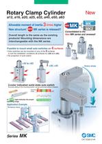
Rotary Clamp Cylinder Allowable moment of inertia 3 times higher New structure! MK series is released!! Overall length is the same as the existing products! Mounting dimensions are interchangeable with the MK series. Possible to mount small auto switches on 4 surfaces • Auto switches can be mounted on any of the 4 surfaces to suit the installation conditions (2 surfaces for o20 and o25). • No projection of auto switch Rotary stroke 2-color indication solid state auto switch Accurate setting of the mounting position can be performed without mistakes A *TEpt light indicates the proper ^^^^^^ operating range. operating range Application Example Clamp stroke
Open the catalog to page 1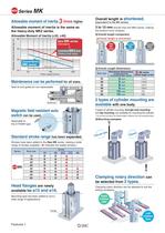
Allowable moment of inertia 3 times higher Allowable moment of inertia is the same as Allowable Moment of Inertia (032, 040) (Heavy-duty type) Piston speed [trim's] Maintenance can be performed for all sizes. Seal kit and guide pin are replaceable. Magnetic field resistant auto ^ Standard stroke range has been expanded. Strokes have been added to the New MK series, making a wide range of strokes available. ("^ indicates the added strokes.) Head flanges are newly Mounting type has been added to suit a wide range of applications. Overall length is shortened. 3 tO 10 mm shorter than the MK2 series,...
Open the catalog to page 2
Model Selection Max. piston speed Note) [mm/s] o12 to o63 Non-rotating accuracy (Clamp part) Rotary angle Horizontal mounting Note) Maximum piston speed indicates the maximum speed possible when employing a standard arm. During unclamping Rotary angle Port side During unclamping Rotary angle During clamping (Retraction end) Non-rotating accuracy Designing Arms When arms are to be made separately, their length and mass should be within the following range. 1. Allowable bending moment Use the arm length and operating pressure within Graph (1) for allowable bending moment loaded piston rod. Operating...
Open the catalog to page 3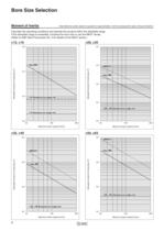
Bore Size Selection Note) Maximum piston speed is equivalent to approximately 1.6x the average piston speed. (Rough Indication) Calculate the operating conditions and operate this product within the allowable range. If the allowable range is exceeded, increase the bore size or use the MK2T series. (Refer to SMC Best Pneumatics No. 3 for details of the MK2T series.) Maximum piston speed [mm/s] Maximum piston speed [mm/s] Maximum piston speed [mm/s] Maximum piston speed [mm/s]
Open the catalog to page 4
Bore Size Selection Note) Maximum piston speed is equivalent to approximately 1.6x the average piston speed. (Rough Indication) Calculation example when arms other than the options are used. • Calculate the moment of inertia of the clamping jig • Calculate the moment of inertia of the arm. ■(Calculation example> when the cylinder bore Size ÍS 032. Clamping jig: h • Calculate the actual moment of inertia. Calculation result (when the bore size is o32 and clamp stroke is 10 mm.) Note 1) Average piston speed = Max. piston speed -M .6 Note 2) Total stroke = Clamp stroke + Rotary stroke Note 3) Total...
Open the catalog to page 5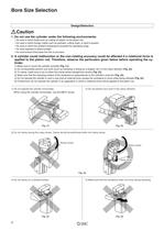
Bore Size Selection Do not use the cylinder under the following environments: • An area in which fluids such as cutting oil splash on the piston rod • An area in which foreign matter such as particles, cutting chips, or dust is present • An area in which the ambient temperature exceeds the operating range • An area exposed to direct sunlight • An environment that poses the risk of corrosion A cylinder could malfunction or the non-rotating accuracy could be affected if a rotational force is applied to the piston rod. Therefore, observe the particulars given below before operating the cy- 1) Make...
Open the catalog to page 6
Rotary Clamp Cylinder: Standard Rotary clamp cylinder Mounting bracket ■ Head flanges are shipped together, (but Bore size* Port thread type Clamp stroke (Refer to the next page Auto switch type •Auto switch type Auto switch multiple side mounting Without auto switch (Built-in magnet) Body option ■ For applicable auto switch models. refer to the below table. ■ Auto switches are shipped * Arms are shipped together, (but not Rotary direction (Unclamp -» Clamp) During unclamping During unclamping During clamping (Retraction end) Applicable Auto Switches/Refer to Best Pneumatics No. 3 for further...
Open the catalog to page 7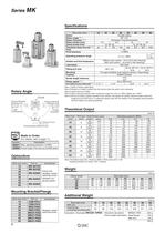
Rotary Angle During unclamping During unclamping Clamp part / \ Non-rotating accuracy During clamping (Retraction end) (Fordetails, referto page 17.] Mounting Bracket/Flange Note 1 ) Refer to Rotary Angle figure. Note 2) Direction of rotation viewed from the rod end when the piston rod is retracting Note 3) Clamp force at 0.5 MPa Note 4) When using the cylinder within a pressure range from 0.61 to 1 MPa, please use -X2071. Note 5) Be sure to install a speed controller to the cylinder, and adjust the cylinder speed to make it within the range from 50 to 200 mm/s. To adjust the speed, start with...
Open the catalog to page 8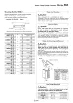
Rotary Clamp Cylinder: Standard Series MK Mounting Bolt for MKB-Z Mounting: Mounting bolt for through-hole type is available. Refer to the following for ordering procedures. Order the actual number of bolts that will be used. Mounting boll Flat washer/ Note) Be sure to use a flat washer to mount cylinders via through-holes. Use a clamp arm that is available as an option. To fabricate a clamp arm, make sure that the allowable bending moment and the inertial moment will be within the specified range. Refer to Graph 1 and 2 on page 1. Ensuring Safety If one side of the piston is pressurized by supplying...
Open the catalog to page 9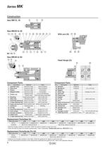
Component Parts Component Parts * Seal kit includes numbers in the table. Order the seal kit, based on each bore size. * Since the seal kit does not include a grease pack, order it separately. Grease pack part no.: GR-S-010 (10 g) Guide pin kit includes numbers in the table. Order the guide pin kit, based on each bore size. For the replacement procedure of the replacement parts/seal and guide pin kits, refer to the Operation Manual.
Open the catalog to page 10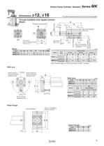
Rotary Clamp Cylinder: Standard Series MK The outline dimensions shown are when the rod is retracted. Through-hole/Both ends tapped common E effective thread depth F Auto switch Minimum bending radius Note) The above figure is with the auto switch (D-M9D) mounted. Rotary direction: L ^orl side Rotary direction: R During unclamping During unclamping During clamping Head flange Head Flange
Open the catalog to page 11All SMC PNEUMATIC catalogs and technical brochures
 Vacuum Unit 2024
99 Pages
 Air Cylinder CJ2 Series
117 Pages
 AS-FS Series
36 Pages
 IDF series
12 Pages
 MHL2 Series
24 Pages
 JCM Serie
18 Pages
 EX245 Series
12 Pages
 Pin Cylinder CJP2/CDJP2/CJP
19 Pages
 5 Port Solenoid Valve VQC
63 Pages
 5 Port Solenoid Valve VQ
79 Pages
 SY
SY268 Pages
 5-p0979-0980-hep500
2 Pages
 5-p0977-0978-aep100
2 Pages
 5-p0966-0971-lmu
5 Pages
 5-p0960-0966-alb900
6 Pages
 5-p0956-0960-ald600
5 Pages
 5-p0948-0950-al800
3 Pages
 es70-44c-vx2
52 Pages
 es50-37-kq2
124 Pages
 ex-pcw
23 Pages
 1-p2124-2152-ex510
29 Pages
 1-p2111-2122-ex500
12 Pages
 1-p2063-2073-ex260
11 Pages
 4-p0147-0178-msu-mds
32 Pages
 es20-230b-crb2
59 Pages
 1-p1869-1878-vp3145
10 Pages
 VP300/500/700 series
42 Pages
 1-p1789-1829-vqz100
41 Pages
 1-p1727-1788-syj300
62 Pages
 5 Port Solenoid Valve S0700
111 Pages
 5 Port Solenoid Valve VF
59 Pages
 5 Port Solenoid Valve SV
127 Pages
 VH
VH9 Pages
 CUJ
CUJ41 Pages
 AL
AL3 Pages
 kj mm
kj mm9 Pages
 AQ
AQ4 Pages
 SY3000/5000-X13
2 Pages
 Series MB
24 Pages
 Series LES
23 Pages
 Series LEFB
16 Pages
 Series PF3W
28 Pages
 Series IDG?A/IDG
56 Pages
 Floating Joint
7 Pages
 Series IZS40/41/42
32 Pages
 Series LEY
7 Pages
 Series VHS
12 Pages
 Series CY1S
28 Pages
 SeriesCQ2/CQS/CQ
4 Pages
 In-line Air Filter
12 Pages
 5 Port Solenoid Valve
60 Pages
 Series CQ2/CQS
2 Pages
 AS series
2 Pages
 corporate guide
13 Pages
 ZP
ZP69 Pages
 ZFA
ZFA14 Pages
 ZA
ZA13 Pages
 MHF
MHF32 Pages
 MHZ
MHZ68 Pages
 CRB
CRB44 Pages
 D
D117 Pages
 RB
RB23 Pages
 CEP
CEP44 Pages
 RSK
RSK30 Pages
 CLK
CLK51 Pages
 GLJ
GLJ65 Pages
 MGJ
MGJ7 Pages
 Mx
Mx36 Pages
 MXH
MXH18 Pages
 My3
My356 Pages
 my1b
my1b20 Pages
 CC
CC15 Pages
 J
J14 Pages
 CQ2
CQ251 Pages
 standard cylinder
84 Pages
 VFN
VFN6 Pages
 SY3000
246 Pages
 SJ3A6
SJ3A618 Pages
 1301/IW
14 Pages
 CHQ/CHDQ
19 Pages
 AC
AC95 Pages
 HAW
HAW4 Pages
 HAA
HAA3 Pages
 ZB
ZB24 Pages
 CRB2
CRB235 Pages


Archived catalogs
 CJ1
CJ15 Pages
 SYJ
SYJ62 Pages
 SJ
SJ78 Pages
 Vacuum Unit ZK2 Series
60 Pages
 SYJ300/500/700 Series
62 Pages
