MHF
1 /32Pages

MHF
1 /32Pages
Catalog excerpts

Low profile air gripper with space-saving design
Open the catalog to page 1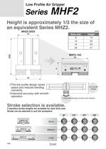
Height is approximately 1/3 the size of ■The low profile design saves space and reduces bending ■ improved accuracy with smooth • Reduced bending moment and vibration Stroke selection is available. 3 standard stroke lengths are available for each bore size. Stroke can be selected to suit the workpiece.
Open the catalog to page 2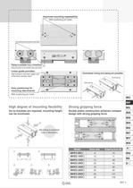
Improved mounting repeatability Piping is available from 2 directions Piping port position can be specified using a part number. Linear guide provides martensitic stainless steel mounting attachments With positioning pin holes Centralized wiring and piping are possible. Axial piping Side piping High degree of mounting flexibility As no brackets are required, mounting height Strong gripping force Double piston construction achieves compact design with strong gripping force.
Open the catalog to page 3
Model Selection Model Selection Selection Procedure Confirm gripping force Confirm gripping point Confirm external force on fingers Confirmation of Gripping Force- •\ Calculation of required gripping force ►(Model selection from gripping force graph) Example Workpiece mass: 0.15 kg Gripping method: External Model selection criteria with respect to workpiece mass • Although differences will exist depending on factors such as shape and the coefficient of friction between attachments and workpieces, select a model which will provide a gripping force 10 to 20 times the weight of the workpiece. (Notel)...
Open the catalog to page 4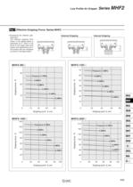
Low Profile Air Gripper Series MHF2 Effective Gripping Force: Series MHF2 ■ Expressing the effective grip- ping force The effective gripping force shown in the graphs below is thrust of one finger when both full contact with the workpiece as shown in the figure below. External Gripping Internal Gripping
Open the catalog to page 5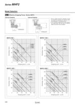
Model Selection Effective Gripping Force: Series MHF2- External Gripping Internal Gripping • The air gripper should be operated so that the amount of overhang "H" will stay within the range given in the graphs below. • If the workpiece gripping point goes beyond the range limits, this will have an adverse effect on the life of the air gripper.
Open the catalog to page 6
Low Profile Air Gripper Seríes MHF2 Confirmation of External Force on Fingers: Series MHF2 L: Distance to the point at which the load is applied (mm) Note) The load and moment values in the table indicate static values. Calculation of allowable external force (when moment load is applied) M (Maximum allowable moment) (N m) (* Unit converted invariable number) Calculation example When a load f = 10 N is operating, which applies pitch moment to point L = 30 mm from the end of the
Open the catalog to page 7
Refer to page 453 for details. Number of auto switches Auto switch Without auto switch (Built-in magnet) Body option Nil: Axial piping type R: Side piping type Applicable Auto Switches/Refer to pages 761 to 809 for further Information on auto switches. Note 1) Take note of hysteresis with 2-color indication type switches. When using, refer to page 471 for auto switch hysteresis.
Open the catalog to page 8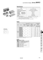
Low Profile Air Gripper Seríes MHF2 Note 1) This is the value when no offset load is applied to the finger. When an offset load is applied to the finger, the maximum value is ±0.15 mm due to the influence of backlash of the rack and pinion. Note 2) Refer to pages 761 to 809 for further information on auto switches. Note 1) At the pressure of 0.5 MPa, when gripping point L is 20 mm. MHK Note 2) Excluding the auto switch mass. ^=== Made to Order |y|HQ Refer to pages 683 to 713 for details.
Open the catalog to page 9
Component Parts Replacement Parts Component Parts Bolts for Body Through-hole Replacement part/Grease pack part no.: * The bolts for body through-hole mounting are attached to the product. They are also provided at an order of 1 piece or more with the above part numbers.
Open the catalog to page 10
Low Profile Air Gripper Seríes MHF2 Component Parts Replacement Parts Bolts for Body Through-hole The bolts for body through-hole mounting are attached to the product. They are also provided at an order of 1 piece or more with the above part numbers. with the body through-holes, use hexagon socket head screws available on the market. Replacement part/Grease pack part no.:
Open the catalog to page 11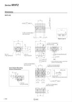
(Mounting thread) Finger opening port Finger closing port (Mounting thread) Auto Switch Mounting Groove Dimensions .auto switch mounting (Mounting thread) * Use the attached hexagon socket head screws for mounting holes. (Attachment mounting thread) Accessory option: Hexagon socket head screw (special screws) '(Mounting thread)
Open the catalog to page 12
Low Profile Air Gripper Seríes MHF2 (Mounting thread) Finger opening port Auto Switch Mounting Groove Dimensions (Mounting thread) auto switch mounting (Mounting thread) : Use the attached hexagon socket head screws for mounting holes. (Attachment mounting thread) Accessory option: Hexagon socket head screw (special screws) '(Mounting thread)
Open the catalog to page 13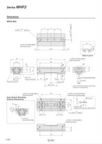
(Mounting thread) Finger opening port Use the attached hexagon socket head screws for mounting holes. (Mounting thread) Auto Switch Mounting Groove Dimensions auto switch mounting ' (Attachment mounting thread) Accessory option: Hexagon socket head screw (special screws) '(Mounting thread)
Open the catalog to page 14
Low Profile Air Gripper Seríes MHF2 (Mounting thread) Finger opening port Finger closing port Auto Switch Mounting Groove Dimensions (Mounting thread) ' (Mounting thread) : Use the attached hexagon socket head screws for mounting holes. (Attachment mounting thread) Accessory option: Hexagon socket head screw (special screws) (Mounting thread)
Open the catalog to page 15
Series MHF2 Dimensions depth 3 MHF2-12D1 42 +0.025 0 depth 3 3H9 ø3H9 +0.030 0 0.3 10.6 2 x M4 x 0.7 thread depth 10 (Mounting thread) 4 58 4 Detail of part A 40 68 2 x M4 x 0.7 thread depth 5 54 15 25 19 20 A (Mounting thread) E 7.7 20 14.8 M5 x 0.8 Finger closing port E 0 –0.1 21 1 1 M5 x 0.8 Finger opening port 2 x ø3.4 through (Mounting hole)∗ 21 2 x ø5.5 +0.1 Close: 0 0 E-E Open: 24±1 ∗ Use the attached hexagon socket head screws for mounting holes. 8 x M3 x 0.5 thread depth 4 44 4 x M4 x 0.7 thread depth 5 (Mounting thread) (Attachment mounting thread) M3 x 0.5 ø5 Auto Switch Mounting Groove...
Open the catalog to page 16All SMC PNEUMATIC catalogs and technical brochures
 Vacuum Unit 2024
99 Pages
 Air Cylinder CJ2 Series
117 Pages
 AS-FS Series
36 Pages
 IDF series
12 Pages
 MHL2 Series
24 Pages
 JCM Serie
18 Pages
 EX245 Series
12 Pages
 Pin Cylinder CJP2/CDJP2/CJP
19 Pages
 5 Port Solenoid Valve VQC
63 Pages
 5 Port Solenoid Valve VQ
79 Pages
 SY
SY268 Pages
 5-p0979-0980-hep500
2 Pages
 5-p0977-0978-aep100
2 Pages
 5-p0966-0971-lmu
5 Pages
 5-p0960-0966-alb900
6 Pages
 5-p0956-0960-ald600
5 Pages
 5-p0948-0950-al800
3 Pages
 es70-44c-vx2
52 Pages
 es50-37-kq2
124 Pages
 ex-pcw
23 Pages
 1-p2124-2152-ex510
29 Pages
 1-p2111-2122-ex500
12 Pages
 1-p2063-2073-ex260
11 Pages
 4-p0147-0178-msu-mds
32 Pages
 es20-230b-crb2
59 Pages
 1-p1869-1878-vp3145
10 Pages
 VP300/500/700 series
42 Pages
 1-p1789-1829-vqz100
41 Pages
 1-p1727-1788-syj300
62 Pages
 5 Port Solenoid Valve S0700
111 Pages
 5 Port Solenoid Valve VF
59 Pages
 5 Port Solenoid Valve SV
127 Pages
 VH
VH9 Pages
 CUJ
CUJ41 Pages
 AL
AL3 Pages
 kj mm
kj mm9 Pages
 AQ
AQ4 Pages
 SY3000/5000-X13
2 Pages
 Series MB
24 Pages
 Series LES
23 Pages
 Series LEFB
16 Pages
 Series PF3W
28 Pages
 Series IDG?A/IDG
56 Pages
 Floating Joint
7 Pages
 Series IZS40/41/42
32 Pages
 Series LEY
7 Pages
 Series VHS
12 Pages
 Series CY1S
28 Pages
 SeriesCQ2/CQS/CQ
4 Pages
 In-line Air Filter
12 Pages
 5 Port Solenoid Valve
60 Pages
 Series CQ2/CQS
2 Pages
 AS series
2 Pages
 corporate guide
13 Pages
 ZP
ZP69 Pages
 ZFA
ZFA14 Pages
 ZA
ZA13 Pages
 MHZ
MHZ68 Pages
 CRB
CRB44 Pages
 D
D117 Pages
 RB
RB23 Pages
 CEP
CEP44 Pages
 RSK
RSK30 Pages
 CLK
CLK51 Pages
 MK
MK20 Pages
 GLJ
GLJ65 Pages
 MGJ
MGJ7 Pages
 Mx
Mx36 Pages
 MXH
MXH18 Pages
 My3
My356 Pages
 my1b
my1b20 Pages
 CC
CC15 Pages
 J
J14 Pages
 CQ2
CQ251 Pages
 standard cylinder
84 Pages
 VFN
VFN6 Pages
 SY3000
246 Pages
 SJ3A6
SJ3A618 Pages
 1301/IW
14 Pages
 CHQ/CHDQ
19 Pages
 AC
AC95 Pages
 HAW
HAW4 Pages
 HAA
HAA3 Pages
 ZB
ZB24 Pages
 CRB2
CRB235 Pages


Archived catalogs
 CJ1
CJ15 Pages
 SYJ
SYJ62 Pages
 SJ
SJ78 Pages
 Vacuum Unit ZK2 Series
60 Pages
 SYJ300/500/700 Series
62 Pages
