

J

J
Catalog excerpts
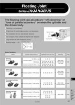
Floating Joint Series Variations Cylinder supply pressure The floating joint can absorb any "off-centering" or "loss of parallel accuracy" between the cylinder and A high level of machining accuracy is unnecessary. The installation time is dramatically reduced. It is compact and is suitable for high tensile stresses. Long service life (with dustproof cover) Applicable bore size (mm) Basic style Flange style Foot style Heavy load Hydraulic cylinder Basic style Flange style Foot style Pneumatic cylinder Basic style (Female thread) Stainless steel type Basic style
Open the catalog to page 1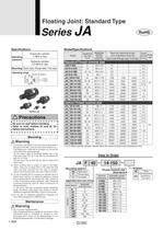
Floating Joint: Standard Type Pneumatic cylinder: Hydraulic cylinder: Mounting Basic style, Flange style, Foot style Operating range I Be sure to read before handling. I Refer to front matters 54 and 55 for . To screw the male threads of the rod Into the female threads of the socket or the case, make sure that It does not bottom out. If the floating joint Is used with Its rod bottom out, the stud will not be able to float, causing damage. For the screw-In depth of the female threads, refer to the dimensions (page 910). As a rule, after the rod bottoms out. The dust cover may be fixed with the...
Open the catalog to page 2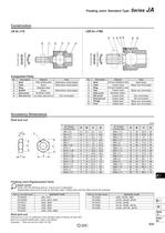
Floating Joint: Standard Type Series J A Accessory Dimensions Floating Joint Replacement Parts Order with the following part no. if dust cover is damaged. Replaceable dust cover is only for the basic style. Flange style and foot style cannot be replaced. Rod end nut (1 pc.) is attached to the standard type of Series JA and JAH. But if it is needed additionally, order it as follows.
Open the catalog to page 3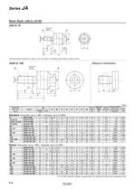
Use the precision spanner for clock 4 mm in the case of mounting male thread of JA6 and JA10. Without C-dimension Option Pneumatic: Up to 1 MPa Hydraulic: Up to 3.5 MPa * For 3.5 MPa hydraulic cylinders, operate within the maximum tension and compression force.
Open the catalog to page 4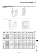
Floating Joint: Standard Type Series J A Standard Pneumatic: Up to 1 MPa Hydraulic: Up to 3.5 MPa Option Pneumatic: Up to 1 MPa Hydraulic: Up to 3.5 MPa * For 3.5 MPa hydraulic cylinders, operate within the maximum tension and compression force.
Open the catalog to page 5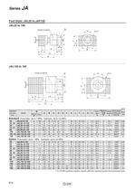
Standard Pneumatic: Up to 1 MPa Hydraulic: Up to 3.5 MPa Option Pneumatic: Up to 1 MPa Hydraulic: Up to 3.5 MPa * For 3.5 MPa hydraulic cylinders, operate within the maximum tension and compression force.
Open the catalog to page 6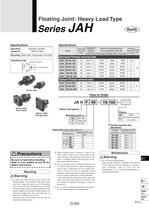
Floating Joint: Heavy Load Type Operating range — Axial center Series JAHL (Foot style) (Flange style) I Be sure to read before handling. I I Refer to front matters 54 and 55 for I 1. To screw the male threads of the rod into the female threads of the socket or the case, make sure that it does not bottom out. If the floating joint is used with its rod bottomed out, the stud will not be able to float, causing damage. For the screw-in depth of the female threads, refer to the dimensions (page 914). As a rule, after the rod bottoms out, back off 1 to 2 turns. The dust cover may be fixed with the...
Open the catalog to page 7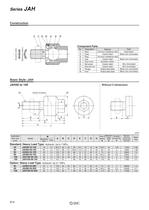
ponent Parts Without C-dimension Standard: Heavy Load Type Hydraulic: Up to 7 MPa Option: Heavy Load Type Hydraulic: Up to 7 MPa
Open the catalog to page 8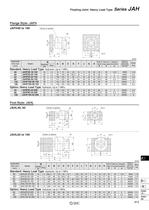
Floating Joint: Heavy Load Type Series Flange Style: JAFH Option: Heavy Load Type Hydraulic: Up to 7 MPa Foot Style: JAHL Option: Heavy Load Type Hydraulic: Up to 7 MPa
Open the catalog to page 9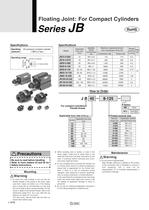
Floating Joint: For Compact Cylinders Air pressure compact cylinder Operating range — Axial center Female thread Applicable bore size (mm) < Thread nominal size I Be sure to read before handling. I I Refer to front matters 54 and 55 for I 1. To screw the male threads of the rod into the female threads of the socket or the case, make sure that It does not bottom out. If the floating joint is used with its rod bottomed out, the stud will not be able to float, causing damage. For the screw-In depth of the female threads, refer to the dimensions (page 917). As a rule, after the rod bottoms out, back...
Open the catalog to page 10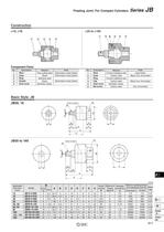
Floating Joint: For Compact Cylinders Series
Open the catalog to page 11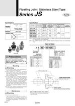
Floating Joint: Stainless Steel Type I Be sure to read before handling. I I Refer to front matters 54 and 55 for I 1. For the screw-in depth of the female threads, refer to the dimensions (page 920). 2. When screwing stud or socket, or case in the driven object, make sure to screw them in the state that dust cover has been removed from the case. If screwing without removing dust cover, duct cover might be broken. 3. To use a floating joint to connect the cylinder rod to a driven body, secure it in place by applying a torque that is appropriate for the thread size. Also, if there is a risk of...
Open the catalog to page 12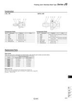
Floating Joint: Stainless Steel Type Series Component Parts Component Parts Replacement Parts Dust cover When the dust cover is damaged and deteriorated, order with the part number as shown below. Rod end nut (1 pc.) is attached to the standard type of Series JS. But if it is needed additionally, order it as follows. For details, refer to page 920.
Open the catalog to page 13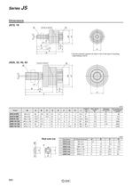
* Use the precision spanner for clock 4 mm in the case of mounting
Open the catalog to page 14All SMC PNEUMATIC catalogs and technical brochures
 Vacuum Unit 2024
99 Pages
 Air Cylinder CJ2 Series
117 Pages
 AS-FS Series
36 Pages
 IDF series
12 Pages
 MHL2 Series
24 Pages
 JCM Serie
18 Pages
 EX245 Series
12 Pages
 Pin Cylinder CJP2/CDJP2/CJP
19 Pages
 5 Port Solenoid Valve VQC
63 Pages
 5 Port Solenoid Valve VQ
79 Pages
 SY
SY268 Pages
 5-p0979-0980-hep500
2 Pages
 5-p0977-0978-aep100
2 Pages
 5-p0966-0971-lmu
5 Pages
 5-p0960-0966-alb900
6 Pages
 5-p0956-0960-ald600
5 Pages
 5-p0948-0950-al800
3 Pages
 es70-44c-vx2
52 Pages
 es50-37-kq2
124 Pages
 ex-pcw
23 Pages
 1-p2124-2152-ex510
29 Pages
 1-p2111-2122-ex500
12 Pages
 1-p2063-2073-ex260
11 Pages
 4-p0147-0178-msu-mds
32 Pages
 es20-230b-crb2
59 Pages
 1-p1869-1878-vp3145
10 Pages
 VP300/500/700 series
42 Pages
 1-p1789-1829-vqz100
41 Pages
 1-p1727-1788-syj300
62 Pages
 5 Port Solenoid Valve S0700
111 Pages
 5 Port Solenoid Valve VF
59 Pages
 5 Port Solenoid Valve SV
127 Pages
 VH
VH9 Pages
 CUJ
CUJ41 Pages
 AL
AL3 Pages
 kj mm
kj mm9 Pages
 AQ
AQ4 Pages
 SY3000/5000-X13
2 Pages
 Series MB
24 Pages
 Series LES
23 Pages
 Series LEFB
16 Pages
 Series PF3W
28 Pages
 Series IDG?A/IDG
56 Pages
 Floating Joint
7 Pages
 Series IZS40/41/42
32 Pages
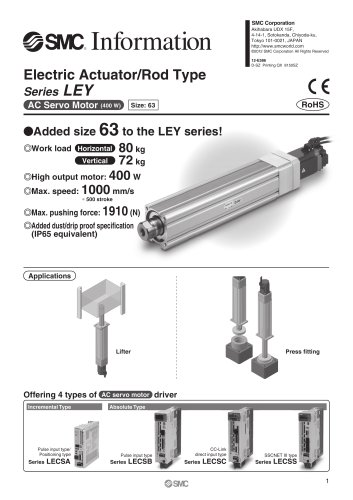 Series LEY
7 Pages
 Series VHS
12 Pages
 Series CY1S
28 Pages
 SeriesCQ2/CQS/CQ
4 Pages
 In-line Air Filter
12 Pages
 5 Port Solenoid Valve
60 Pages
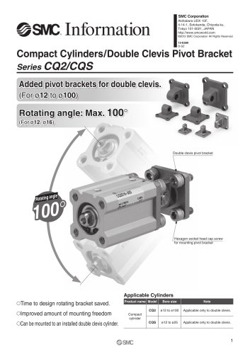 Series CQ2/CQS
2 Pages
 AS series
2 Pages
 corporate guide
13 Pages
 ZP
ZP69 Pages
 ZFA
ZFA14 Pages
 ZA
ZA13 Pages
 MHF
MHF32 Pages
 MHZ
MHZ68 Pages
 CRB
CRB44 Pages
 D
D117 Pages
 RB
RB23 Pages
 CEP
CEP44 Pages
 RSK
RSK30 Pages
 CLK
CLK51 Pages
 MK
MK20 Pages
 GLJ
GLJ65 Pages
 MGJ
MGJ7 Pages
 Mx
Mx36 Pages
 MXH
MXH18 Pages
 My3
My356 Pages
 my1b
my1b20 Pages
 CC
CC15 Pages
 CQ2
CQ251 Pages
 standard cylinder
84 Pages
 VFN
VFN6 Pages
 SY3000
246 Pages
 SJ3A6
SJ3A618 Pages
 1301/IW
14 Pages
 CHQ/CHDQ
19 Pages
 AC
AC95 Pages
 HAW
HAW4 Pages
 HAA
HAA3 Pages
 ZB
ZB24 Pages
 CRB2
CRB235 Pages


Archived catalogs
 CJ1
CJ15 Pages
 SYJ
SYJ62 Pages
 SJ
SJ78 Pages
 Vacuum Unit ZK2 Series
60 Pages
 SYJ300/500/700 Series
62 Pages
