Catalog excerpts

Applicable for the high-temperature environments Ambient temperature : Max. 45°C Inlet air temperature : Max. 65°C (24% increase compared to the current model)
Open the catalog to page 1
Refrigerated Air Dryer IDF Series temperature environments New stainless steel heat exchanger helps reduce the load of the compressor
Open the catalog to page 2
Refrigerated Air Dryer IDF Series Series Variations Model Rated inlet condition Rated ambient temperature Port size Optional accessories Auto Drain Valve Longer life, Higher resistance to foreign matter Non-sliding part reduces the catching of foreign matter Shape prevents condensate accumulation Diaphragm type Poppet type Condensate and foreign matter are discharged completely. Easier maintenance One-touch mounting and removal of the bowl is possible without using any tools. Release the lock by sliding the lock button down while holding the body. Then, rotate the bowl guard and pull down...
Open the catalog to page 3
Refrigerated Air Dryer IDF Series Protect Pneumatic Equipment from Moisture! An air dryer removes the vapor from the moist compressed air delivered by the compressor and prevents it from causing the pneumatic equipment to fail. ¡ alfunctioning of valves and M actuators caused by dripping grease Effects of moisture on equipment ¡Generation of water droplets ¡ ecomposition of auto drain caused D by rusting inside pipes Main line filter Mist separator Control panel The malfunction of air bearings of 3D measurement device, etc. Washing machine
Open the catalog to page 4
Read the correction factors ® to © suitable to the operating conditions. *1 Values obtained from the table below Corrected air flow capacity = 6.0 m3/min (ANR) 1 (0.78 x 1.05 x 0.92 x 1.00) = 7.96 m3/min (ANR) The 60 Hz power supply frequency model with an air flow capacity which exceeds the corrected air flow capacity of 7.96 m3/min (ANR) is the IDF70. ^ Calculate the corrected air flow capacity. Obtain the corrected air flow capacity from the following formula. Corrected air flow capacity = Air flow rate 1 (Correction factor @ x ® x © x ©) ^ Select the model. Select the model with air...
Open the catalog to page 5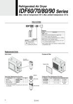
Replacement Parts Voltage Symbol Options Symbol * When multiple options are combined, indicate symbols in alphabetical order. Dustproof filter Auto Drain Replacement Part Nos. Element Dustproof Filter Replacement Part Nos. Description *1 A bowl O-ring is included. A One-touch fitting for connecting the drain tube is not included.
Open the catalog to page 6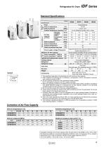
Correction of Air Flow Capacity Refrigerated Air Dryer IDF Series Inlet air pressure [MPa] Outlet air pressure dew point [°C] MPa Model Specifications Calculation example: The air flow capacity when the dew point of the IDF60 is set to 10°C under the following conditions is calculated. [Operating conditions: Inlet air temperature: 35°C, Ambient temperature: 35°C, Inlet air pressure: 0.6 MPa, Power supply frequency: 50 Hz] 5.3 m3/min (ANR) x 1.00 x 0.94 x 0.92 = 4.6 m3/min (AnR) 1 The operating range does not guarantee use with normal air flow capacity. *2 ANR indicates the following set of...
Open the catalog to page 7
IDF Series Construction (Air/Refrigerant Circuit) Humid, hot air coming into the air dryer will be cooled Evaporation thermometer down by a cooler re-heater (heat exchanger). Water condensed at this time will be removed from the air by an auto drain and drained out automatically. Air separated from the water will be heated by a cooler reheater (heat exchanger) to obtain the dried air, which goes through to the outlet side. Cooler re-heater Ball valve Auto drain Capillary tube High pressure switch Volume control valve Pressure switch Drain outlet Accumulator Compressor for refrigeration...
Open the catalog to page 8
In addition to power supply connection, terminal blocks for operating, error, and remote operation signals are available. • The operating and error signals are no-voltage contact style. Operating signal...During operation: contact “close”, During stop: contact “open” Error signal.During error: contact “close”, During stop: contact “open” Contact capacity.Rated load voltage: 240 VAC or less/24 VDC or less Max. load current: 5 A (Resistance load)/2 A (Induction load) Min. applicable load: 20 VDC, 3 mA • Power supply voltage is applied to the remote operation contact. The external switch is to...
Open the catalog to page 9
IDF Series Specific Product Precautions 1 Be sure to read this before handling the products. Refer to the back cover for Safety Instructions. For air preparation equipment precautions, refer to the Handling Precautions for SMC Products and the Operation Manual on the SMC website: http://www.smcworld.com |_Power Supply • Avoid locations where the air dryer will be in direct contact with wind or rain. (Avoid locations where relative humidity is 85% or more.) • Avoid locations where water, water vapor, salt water, or oil may splash on the product. • Avoid locations where dust or other...
Open the catalog to page 10
IDF Series Specific Product Precautions 2 Be sure to read this before handling the products. Refer to the back cover for Safety Instructions. For air preparation equipment precautions, refer to the Handling Precautions for SMC Products and the Operation Manual on the SMC website: http://www.smcworld.com Protection Circuit A Caution When the air dryer is operated in the following cases, the protection circuit will activate, the light will turn off and the air dryer will come to stop. • The compressed air temperature is too high. • The compressed air flow rate is too high. • The ambient...
Open the catalog to page 11
Safety Instructions These safety instructions are intended to prevent hazardous situations and/or equipment damage. These instructions indicate the level of potential hazard with the labels of “Caution,” “Warning” or “Danger.” They are all important notes for safety and must be followed in addition to International Standards (ISO/IEC)∗1), and other safety regulations. Caution indicates a hazard with a low level of risk which, if not avoided, could result in minor or moderate injury. Warning indicates a hazard with a medium level of risk which, if not avoided, could result in death or...
Open the catalog to page 12All SMC PNEUMATIC catalogs and technical brochures
-
Vacuum Unit 2024
99 Pages
-
Air Cylinder CJ2 Series
117 Pages
-
AS-FS Series
36 Pages
-
MHL2 Series
24 Pages
-
JCM Serie
18 Pages
-
EX245 Series
12 Pages
-
Pin Cylinder CJP2/CDJP2/CJP
19 Pages
-
5 Port Solenoid Valve VQC
63 Pages
-
5 Port Solenoid Valve VQ
79 Pages
-
SY
268 Pages
-
5-p0979-0980-hep500
2 Pages
-
5-p0977-0978-aep100
2 Pages
-
5-p0966-0971-lmu
5 Pages
-
5-p0960-0966-alb900
6 Pages
-
5-p0956-0960-ald600
5 Pages
-
5-p0948-0950-al800
3 Pages
-
es70-44c-vx2
52 Pages
-
es50-37-kq2
124 Pages
-
ex-pcw
23 Pages
-
1-p2124-2152-ex510
29 Pages
-
1-p2111-2122-ex500
12 Pages
-
1-p2063-2073-ex260
11 Pages
-
4-p0147-0178-msu-mds
32 Pages
-
es20-230b-crb2
59 Pages
-
1-p1869-1878-vp3145
10 Pages
-
VP300/500/700 series
42 Pages
-
1-p1789-1829-vqz100
41 Pages
-
1-p1727-1788-syj300
62 Pages
-
5 Port Solenoid Valve S0700
111 Pages
-
5 Port Solenoid Valve VF
59 Pages
-
5 Port Solenoid Valve SV
127 Pages
-
VH
9 Pages
-
CUJ
41 Pages
-
AL
3 Pages
-
kj mm
9 Pages
-
AQ
4 Pages
-
SY3000/5000-X13
2 Pages
-
Series MB
24 Pages
-
Series LES
23 Pages
-
Series LEFB
16 Pages
-
Series PF3W
28 Pages
-
Series IDG?A/IDG
56 Pages
-
Floating Joint
7 Pages
-
Series IZS40/41/42
32 Pages
-
Series LEY
7 Pages
-
Series VHS
12 Pages
-
Series CY1S
28 Pages
-
SeriesCQ2/CQS/CQ
4 Pages
-
In-line Air Filter
12 Pages
-
5 Port Solenoid Valve
60 Pages
-
Series CQ2/CQS
2 Pages
-
AS series
2 Pages
-
corporate guide
13 Pages
-
ZP
69 Pages
-
ZFA
14 Pages
-
ZA
13 Pages
-
MHF
32 Pages
-
MHZ
68 Pages
-
CRB
44 Pages
-
D
117 Pages
-
RB
23 Pages
-
CEP
44 Pages
-
RSK
30 Pages
-
CLK
51 Pages
-
MK
20 Pages
-
GLJ
65 Pages
-
MGJ
7 Pages
-
Mx
36 Pages
-
MXH
18 Pages
-
My3
56 Pages
-
my1b
20 Pages
-
CC
15 Pages
-
J
14 Pages
-
CQ2
51 Pages
-
standard cylinder
84 Pages
-
VFN
6 Pages
-
SY3000
246 Pages
-
SJ3A6
18 Pages
-
1301/IW
14 Pages
-
CHQ/CHDQ
19 Pages
-
AC
95 Pages
-
HAW
4 Pages
-
HAA
3 Pages
-
ZB
24 Pages
-
CRB2
35 Pages
-
CJ1
5 Pages
-
SYJ
62 Pages
-
SJ
78 Pages
Archived catalogs
-
SYJ300/500/700 Series
62 Pages
-
Vacuum Unit ZK2 Series
60 Pages


