GLJ
1 /65Pages

GLJ
1 /65Pages
Catalog excerpts

Fine Lock Cylinders/Lock-up Cylinder Locking in both directions is possible. Locking in either side of cylinder stroke is (The lock-up cylinder can be locked only in one (Lock-up cylinders are spring locking only.) Series Variations Fine lock cylinders Lock-up cylinder Bore size
Open the catalog to page 1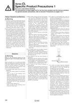
Specific Product Precautions 1 Be sure to read before handling. The precautions on these pages are for the fine lock cylinders and the lock-up cylinders. For general actuator precautions, refer to Actuator Precautions on pages 3 to 7. Design of Equipment and Machinery 1. Construct so that the human body will not come into direct contact with driven objects or the moving parts of locking cylinders. If there is a risk of contact, provide safety measures such as a cover or a system that uses sensors that will activate an emergency stop before contact is made. 2. Use a balance circuit in which lurching...
Open the catalog to page 2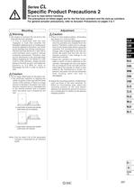
Specific Product Precautions 2 Be sure to read before handling. The precautions on these pages are for the fine lock cylinders and the lock-up cylinders. For general actuator precautions, refer to Actuator Precautions on pages 3 to 7. load with the lock released. • If this is performed with the lock engaged, a load that exceeds the allowable rotational force or holding force would be applied to the piston rod, which could damage the locking mechanism. The fine lock and Series CL1 with 040 to 0100 cylinders have a built-in manual unlocking mechanism. Therefore, they can be maintained in the unlocked...
Open the catalog to page 3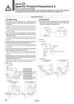
Specific Product Precautions 3 Be sure to read before handling. The precautions on these pages are for the fine lock cylinders and the lock-up cylinders. For general actuator precautions, refer to Actuator Precautions on pages 3 to 7. Pneumatic Circuit 1.Be certain to use an pneumatic circuit which will apply balancing pressure to both sides of the piston when in a locked stop. In order to prevent cylinder lurching after a lock stop, when restarting or when manually unlocking, a circuit should be used to which will apply balancing pressure to both sides of the piston, thereby canceling the force...
Open the catalog to page 4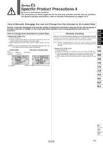
Specific Product Precautions 4 Be sure to read before handling. The precautions on these pages are for the fine lock cylinders and the lock-up cylinders. For general actuator precautions, refer to Actuator Precautions on pages 3 to 7. How to Manually Disengage the Lock and Change from the Unlocked to the Locked State The lock is manually disengaged at the time the cylinder is shipped from the factory. Because the lock will not operate in this state, make sure to change it to the locked state before operation, after having adjusted the axial center for How to Change from Unlocked to Locked State...
Open the catalog to page 5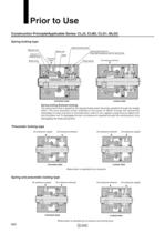
P0595-P0668-E.qxd 08.11.17 2:57 PM Page 600 Prior to Use Construction Principle/Applicable Series: CLJ2, CLM2, CLG1, MLGC Spring locking type Tapered brake piston Release port Pressurized lock port (Plug with breathing hole for spring lock) Brake arm Fulcrum A (Rotary axis) Roller Air pressure supply Brake shoe Brake spring Application point C Air pressure exhaust Power point B Unlocked state Locked state Spring locking (Exhaust locking) The spring force that is applied to the tapered brake piston becomes amplified through the wedge effect. This force becomes further amplified to the power of...
Open the catalog to page 6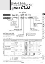
Fine Lock Cylinder Double Acting, Single Rod With auto switch With auto switch* (Built-in magnet) Mounting style Bore size Built-in Magnet Cylinder Model If a built-in magnet cylinder without an auto switch is required, there is no need to enter the symbol for the auto switch. Port location Refer to page 602 for details. Number of auto switches Auto switch Without auto switch 1 For the applicable auto switch model, refer to the table below. Lock operation Applicable AutO Switch/Refer to pages 1719 to I827 for further information on auto switches. 1 Water resistant type auto switches can be mounted...
Open the catalog to page 7
Provided with a compact lock intermediate stop, emergency stop, and drop prevention. Locking in both directions The piston rod can be locked in either direction of its cylinder stroke. Maximum piston speed: that it is within the allowable kinetic energy Head Cover Port Location Either perpendicular to the cylinder axis or in-line with the cylinder axis is available for basic style. Made to Order Specifications (For details, refer to page 1836.) Refer to pages 608 to 610 for cylinders with auto switches. ■ Minimum auto switch mounting stroke ■ Proper auto switch mounting position (detection at...
Open the catalog to page 8
Fine Lock Cylinder Double Acting, Single Rod SeneS A Caution/Allowable Kinetic Energy when Locking * Mounting nut and rod end nut are included in the basic mass. ** Mounting nut is not included in double clevis style. Stopping Accuracy (Not including tolerance of control system.) (mm) Solenoid valve: Lock port mounting Recommended Pneumatic Circuit/Caution on Handling ■ For detailed specifications of the fine . lock cylinder, Series CLJ2 mentioned ' above, refer to pages 596 to 599. ' . In terms of specific load conditions, this allowable kinetic energy is equivalent to a load of 3.7 kg in mass,...
Open the catalog to page 9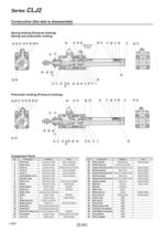
Construction (Not able to disassemble) Spring locking (Exhaust locking) Spring and pneumatic locking Pneumatic locking (Pressure locking) Component Parts
Open the catalog to page 10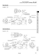
P0595-P0668-E.qxd 08.11.17 2:57 PM Page 605 Fine Lock Cylinder Double Acting, Single Rod Series CLJ2 Basic Style (B) CLJ2B16- E -D P ø Silencer CLJ2 Spring lock CLM2 M5 x 0.8 pressurized locking port Pneumatic locking and spring and pneumatic locking Piping port M5 x 0.8 Manual unlocking cam M5 x 0.8 unlocking port Unlocked when pressurized Lock nut CL1 Head cover port in axial direction (R) M5 x 0.8 Rod side cylinder port M5 x 0.8 Head side cylinder port M14 x 1.0 MLGC CNG MNB ø 0 18.3 –0.3 ø M6 x 1.0 Width across flats 10 CLG1 18.3 CNA 0 –0.3 CNS 111 + Stroke 150 + Stroke CLS CLQ RLQ Axial...
Open the catalog to page 11
P0595-P0668-E.qxd Series 08.11.17 2:57 PM Page 606 CLJ2 Rod Side Flange Style (F) CLJ2F16- E -D P ø8 Silencer Spring lock Piping port M5 x 0.8 Head cover port in axial direction (R) Manual unlocking cam M5 x 0.8 pressurized locking port Pneumatic locking and spring and pneumatic locking M5 x 0.8 unlocking port Unlocked when pressurized M5 x 0.8 Lock nut Rod side cylinder port M14 x 1.0 M6 x 1.0 M5 x 0.8 ø Width across flats 10 0 18.3–0.3 ø Head side cylinder port 0 18.3–0.3 2 x ø5.5 Mounting hole Double Clevis Style (D) CLJ2D16- 111 + Stroke 150 + Stroke ∗ Clevis pin and retaining ring are shipped...
Open the catalog to page 12All SMC PNEUMATIC catalogs and technical brochures
 Vacuum Unit 2024
99 Pages
 Air Cylinder CJ2 Series
117 Pages
 AS-FS Series
36 Pages
 IDF series
12 Pages
 MHL2 Series
24 Pages
 JCM Serie
18 Pages
 EX245 Series
12 Pages
 Pin Cylinder CJP2/CDJP2/CJP
19 Pages
 5 Port Solenoid Valve VQC
63 Pages
 5 Port Solenoid Valve VQ
79 Pages
 SY
SY268 Pages
 5-p0979-0980-hep500
2 Pages
 5-p0977-0978-aep100
2 Pages
 5-p0966-0971-lmu
5 Pages
 5-p0960-0966-alb900
6 Pages
 5-p0956-0960-ald600
5 Pages
 5-p0948-0950-al800
3 Pages
 es70-44c-vx2
52 Pages
 es50-37-kq2
124 Pages
 ex-pcw
23 Pages
 1-p2124-2152-ex510
29 Pages
 1-p2111-2122-ex500
12 Pages
 1-p2063-2073-ex260
11 Pages
 4-p0147-0178-msu-mds
32 Pages
 es20-230b-crb2
59 Pages
 1-p1869-1878-vp3145
10 Pages
 VP300/500/700 series
42 Pages
 1-p1789-1829-vqz100
41 Pages
 1-p1727-1788-syj300
62 Pages
 5 Port Solenoid Valve S0700
111 Pages
 5 Port Solenoid Valve VF
59 Pages
 5 Port Solenoid Valve SV
127 Pages
 VH
VH9 Pages
 CUJ
CUJ41 Pages
 AL
AL3 Pages
 kj mm
kj mm9 Pages
 AQ
AQ4 Pages
 SY3000/5000-X13
2 Pages
 Series MB
24 Pages
 Series LES
23 Pages
 Series LEFB
16 Pages
 Series PF3W
28 Pages
 Series IDG?A/IDG
56 Pages
 Floating Joint
7 Pages
 Series IZS40/41/42
32 Pages
 Series LEY
7 Pages
 Series VHS
12 Pages
 Series CY1S
28 Pages
 SeriesCQ2/CQS/CQ
4 Pages
 In-line Air Filter
12 Pages
 5 Port Solenoid Valve
60 Pages
 Series CQ2/CQS
2 Pages
 AS series
2 Pages
 corporate guide
13 Pages
 ZP
ZP69 Pages
 ZFA
ZFA14 Pages
 ZA
ZA13 Pages
 MHF
MHF32 Pages
 MHZ
MHZ68 Pages
 CRB
CRB44 Pages
 D
D117 Pages
 RB
RB23 Pages
 CEP
CEP44 Pages
 RSK
RSK30 Pages
 CLK
CLK51 Pages
 MK
MK20 Pages
 MGJ
MGJ7 Pages
 Mx
Mx36 Pages
 MXH
MXH18 Pages
 My3
My356 Pages
 my1b
my1b20 Pages
 CC
CC15 Pages
 J
J14 Pages
 CQ2
CQ251 Pages
 standard cylinder
84 Pages
 VFN
VFN6 Pages
 SY3000
246 Pages
 SJ3A6
SJ3A618 Pages
 1301/IW
14 Pages
 CHQ/CHDQ
19 Pages
 AC
AC95 Pages
 HAW
HAW4 Pages
 HAA
HAA3 Pages
 ZB
ZB24 Pages
 CRB2
CRB235 Pages


Archived catalogs
 CJ1
CJ15 Pages
 SYJ
SYJ62 Pages
 SJ
SJ78 Pages
 Vacuum Unit ZK2 Series
60 Pages
 SYJ300/500/700 Series
62 Pages
